Practical 1.1 - Hydrostatics
| Site: | learnonline |
| Course: | Introduction to Water Engineering |
| Book: | Practical 1.1 - Hydrostatics |
| Printed by: | Guest user |
| Date: | Wednesday, 10 June 2026, 9:59 AM |
Description
Practical 1.1 - Hydrostatics
Introduction
The aim of this experiment is to demonstrate the principles of hydrostatic forces on submerged planes.

Lock gates, such as this one from Blanchetown, South Australia, are an example of where it may be necessary to calculate such hydrostatic forces.
But how do you calculate such pressure measurements?
In this experiment, you will combine your mechanics knowledge, with what you know about hydrostatic forces, to determine the moment generated by water pressure in three different tanks (bays) with rectangular, circular and triangular gates.
The pressure on a submerged surface (in this case a gate) creates a distributed load, which can be considered to be an equivalent point load (single force) acting through the centre of pressure.
By converting the distributed load to an equivalent single force, and knowing the location where that force acts on the surface, you can determine the moment generated by the water pressure.
Watch this short video of the locks operating on the Panama Canal.
About the Equipment
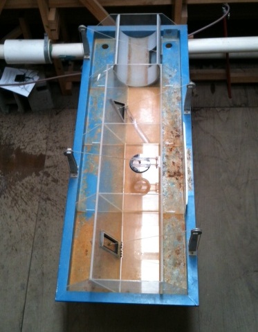 In this experiment, we will use special equipment for measuring hydrostatic force. It consists of a series of tanks, each with a different type of hinged gate on its side. The gates are connected to a known weight by a string, which applies a point force to the gate (and therefore a moment about the hinge) in such an arrangement that it either holds the gate shut or pulls it open.
Apparatus
In this experiment, you will see several tanks, each with a hinged gate on the side. The gates are connected to a known weight by a string (W1, W2 or W3), which applies a point force to the gate (and therefore a moment about the hinge) in such an arrangement that it either holds the gate shut or pulls it open. In each case, an opposing force is created by filling the tank with water. Depending on the arrangement of the gate, the hydrostatic force either forces the gate to open, or keeps it closed.
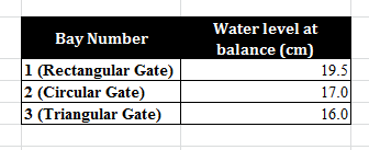
The hydrostatic pressure will be determined by measuring, with a ruler, the “critical water depth” at which the hydrostatic force creates a moment about the hinge that is in balance with the weight.
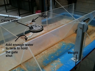
Two more tanks in this experiment are shown below. In these tanks the weight holds the gate closed and then water is added to the tank to the point where the gates open.


The top tank has a rectangle door that will be opened when the hydrostatic force in the tank is greater than the weight.
The lower tank has a triangle door that will be opened when the hydrostatic force in the tank is greater than the weight.
Experimental Method
Watch this video to see how the hydrostatics experiments were performed.
You need to examine the experimental rig to determine the system by which the hydrostatic force is balanced by the hanging weight in each case.
Note the dimensions of each shape and all relevant angles and distances to strings, walls, hinges etc. (see attached ½-scale drawing in Data for Analysis).
You are required to OBSERVE the measurements being performed on the bays, but only “write up” one of them.
Bay-Specific Methods
Bay 1 - Rectangular
Watch as we apply the weight (W1) to the string and while keeping the gate sealed against leakage. Then the trough is filled until the water level, which produces a balanced system, is reached.
The observed water depth that this occurs is recorded.
Bay 2 - Circular
In this bay we fill the trough until the water level approximates the level of hinge. We then apply the weight (W2) to the string and syphon water from the trough until leakage from the gate indicates that the balance situation is near. You then need to observe the water depth at balance, but be quick, as the gate will open immediately after balance has occurred.
The observed water depth that this occurs is recorded.
Bay 3 - Triangle
As for Bay 1 except weight W3 is used.
Data for Analysis
Remember: Select only one tank system to analyse
The hydrostatic experiment drawings can be accessed here.
Raw data
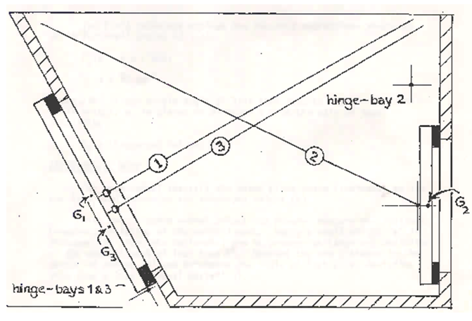
The gate weights are:-
BAY I (rectangular gate): 2.45 N
BAY II (circular gate) : 1.96 N
BAY III (triangular gate) : 2.60 N
These forces act through the points G1, G2 and G3 as shown in the diagram.
Calculations
By measuring the water depth at the critical point (i.e. when the gate opened) you can assume that at this point in time, the moment generated by the hydrostatic force was in balance with the other moments acting on the gate. Shortly after that, the water level changed, creating an imbalance in moments that ultimately forced the gate to swing open.
You are required to combine your mechanics knowledge and your understanding of hydrostatic forces in order to predict the water depth that would generate the critical “balanced moment” state, and compare this with the observed water depth at the critical point.
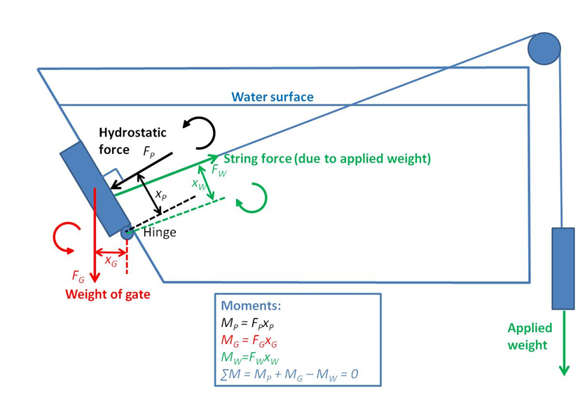
The example in the image above shows how you go about calculating the moments in this experiment – however, each gate system is slightly different so you will need to build up the picture of forces and moments according to the particular gate you have chosen to analyse.
The gate experiences three main forces: the force due to its own weight (FG), the force due to the applied weight through the string (FW) and the hydrostatic force (FP). Each of these forces generates a moment about the hinge, proportional to the perpendicular distance from the line of action of the force to the centre of the hinge. You will need to determine two of these distances (XW ang XG) by measuring directly off the scale drawing provided.
At the critical point, the moments are balanced. In the example shown above, MP and MG operate in the same direction (counter-clockwise), opposing the moment MW generated by the string force. By setting the sum of the moments equal to zero, you can solve for MP as you have been given the necessary information to calculate MG and MW.
Once you know the moment MP, you need to use this to determine the water depth. This means you must develop an expression for the force FP as a function of water depth, starting with the general formula for hydrostatic force:

Next, you need to develop an expression for xP as a function of water depth, starting with the general formula for the location of hydrostatic force:
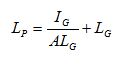
Once you have determined expressions for FP and xP as a function of water depth, you can multiply the two terms together to determine MP as a function of water depth. Because you have been able to calculate MP by balancing moments (as per above) this will allow you to predict the water depth at the critical point.
As with other experiments, you should report on the relative (%) difference between observed and predicted values and discuss possible reasons for any discrepancy.
TASK 1:
Determine, for the water level at balance in each case, the hydrostatic force (F) operating, the location of the centre of pressure (LP) on the gate and the direction of the line of action of the force F (acting through LP).
TASK 2:
Evaluate the moment of the force F about the axis of the hinge. This must equal the moment of the string force W about the axis of the hinge plus or minus (depending on which gate you are calculating) the moment of the gate weight force about the hinge. At the critical depth the moments should be balanced; therefore you can calculate the required magnitude of the string force.
TASK 3:
Compare your computed values for W1, W2 or W3 (depending on the gate and weight you are using) with their actual values - 12.9N, 10. 2N, 13.0N respectively - and suggest possible causes for any discrepancies observed.