MATLAB Project - Whitworth Mechanism
| Site: | learnonline |
| Course: | MATLAB |
| Book: | MATLAB Project - Whitworth Mechanism |
| Printed by: | Guest user |
| Date: | Tuesday, 16 December 2025, 7:23 AM |
Description
MATLAB Project - Whitworth Mechanism
Whitworth Quick Return Mechanism
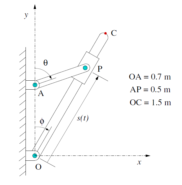
Consider the Whitworth Quick-Return Mechanism illustrated, which is driven by the crank ("driving link") AP. The slider at P is free to slide along the "driven link" OC.
Assume that, at time t = 0, the crank and driven link are in the vertical position (so that θ= 0, φ= 0) and thereafter the crank AP rotates in a clockwise direction at 20 revolutions per minute about A.
Project tasks
There are 5 project tasks to be completed as part of this project.
You will be working collaboratively to solve these and will be working in a wiki (and forum) to complete your report.
1. simulate.m
Produce the following commands in a Matlab M-Fille named simulate.m, and then run it. Watch carefully the behaviour of the crank and the driven link during these two cycles.
% This program simulates the mechanical system
figure(1)
THETA=linspace(0,2*pi,101);
for t=0:0.03:6
theta=2*pi*t/3;
% find coordinates of P
Xp=0.5*sin(theta); Yp=0.7+0.5*cos(theta);
% find coordinates of C
Xc=7.5*sin(theta)/sqrt(74+70*cos(theta));
Yc=(10.5+7.5*cos(theta))/sqrt(74+70*cos(theta));
axis([-1.2 1.2 -0.1 1.7]), axis('equal'), axis manual
hold on
plot([0 0],[0 0.7],'b')
plot([0 Xp],[0.7 Yp],'r') % (1)
plot([0 Xc],[0 Yc],'g')
plot(0.5*cos(THETA),0.7+0.5*sin(THETA),'k:') % (2)
hold off
pause(0.1), clf
end
2. Explain
Explain precisely what the two arrays in each of (1) and (2) represent, and what the commands produce.
Why is axis manual included, and what would happen if it was omitted?
Why is clf included, and what would happen if it was omitted?
4. Calculations
If s(t) is the distance of the slider along the driven link from O, and φ(t) is as shown (it takes both positive and negative values), use simple explanations (no calculus!) to determine the maximum and minimum values of both s(t) and φ(t), and the times they occur.
5. function.m files
Create three function M-files phi.m , angvel.m , angacc.m , to represent the angle φ(t) [radians], the angular velocity φ'(t) [radians/sec] and the angular acceleration φ''(t) [radians/sec2]. Others may be needed later. Write one script M-le named mech.m which
- uses diff in the Symbolic Math Toolbox to nd simple expressions for φ'(t) and φ''(t) which can be copied into the function M-les mentioned above.
- uses plot to plot the distance s(t) over one cycle.
- uses fplot to plot separately the angle (t), the angular velocity φ'(t) and the angular acceleration φ''(t), over one cycle starting at t = 0.
- uses fminbnd to determine the maximum and minimum values of the angular acceleration φ''(t)(and times). (These are often needed by engineers to determine extreme forces.)
- uses fzero to find the first two times t1, t2 when the angle is forty-five degrees, and then calculates the angular velocity at each time.
- calculates, in a single cycle, the total time spent by the driven link moving to the left, and also moving to the right. (There are various ways you could do this).
Group Spaces
A forum and a wiki exist for your group to work in to complete the project. These spaces are private to you and your group members. The spaces will be ready for your groups to use about a week after you commence your studies.
You will also be able to hold 1 or more real time meetings with your group members using a virtual classroom environment.
The Groups are:
| Red | Blue | Green | Yellow |
| name | name | name | name |
| name | name | name | name |
| name | name | name | name |
Group Forum
also embedded below.
Group Wiki
Assessment Questions?
The project counts for 10% of your grade. The marking will take into account
- your documentation of the analysis of the problem,
- your MATLAB programs,
- your MATLAB output,
- the correctness of your solutions, and
- the presentation of the whole report.
If you have any questions about how you will be assessed, please raise them in this MATLAB Project forum, also embedded below.
Submit
Your work is to be presented in a group wiki - so instead of submitting, your wiki editing rights will cease to allow your work to be marked.
Wikis are the only way that you can collaboratively generate a product when working at a distance in groups. You are able to add images and other media to the wiki by first giving it a url. An easy way to do this is to make a post to your group forum and add the files as attachments to the forum. You then right click on image to obtain the url, then add to wiki.
The basic layout of the wiki should be
- an opening page with the names of the group members and a table of contents,
- a full description of the main findings of the project, including the derivations and calculations in with appropriate comments on their significance,
- a record of your properly documented M-Files written for the project,
- all required plots, properly labelled.

