Creating your first display
The following are a few simple projects you can do with the Duinotech kit (or similar Arduino compatible device)
One digit 7-segment display
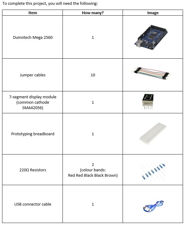
The SMA42056 element is called a 7-segment display, because it has seven separate LEDs integrated into the module. The seven segments can be switched on and off individually to create numbers and patterns.
The general structure is:
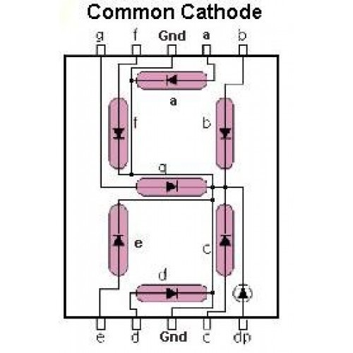
Image source https://www.robomart.com/7-segment-led-display-common-cathode
The module has 10 pins along two sides, that you use to plug into the breadboard. The side with the product code printed on it has pins 1 to 5, the opposite side has pins 6 to 10. Pins 3 and 8 are the two ground (gnd) pins, which will connect to one of the gnd pins on the Mega board. Two resistors will be used as current limiters, so that we don't risk overloading the LEDs.
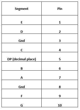
The pins correspond to the segments:
Assembling the components
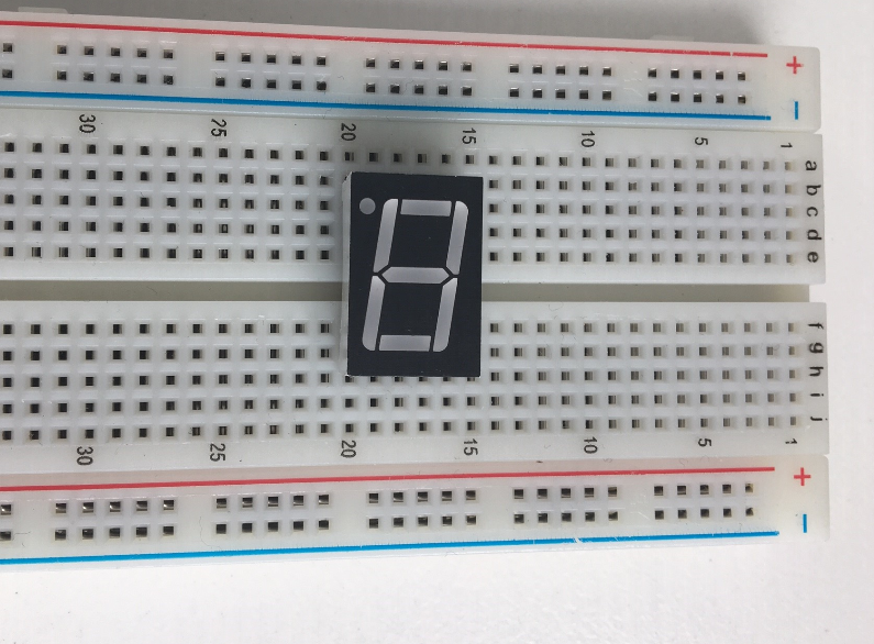
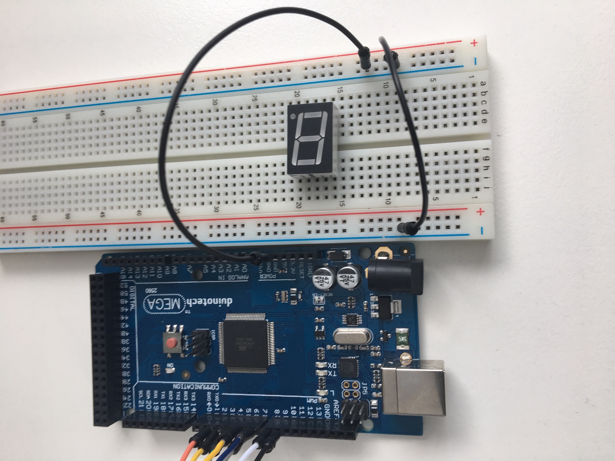
STEP 1
- Insert the module into the breadboard
- Make sure that both sets of pins are within the two inner rails on the breadboard
- (- sign & blue line indicate the negative rail)
- (+ sign & red line indicate the positive rail)
- Take note of the side that the product code & decimal point are positioned on. This helps you correctly identify your segments and pin numbers
STEP 2
- Connect the gnd on the Duinotech Mega Board to the -ve rail on the breadboard. Connect both -ve rails with one jumper lead (because it is a common cathode device, there are two pins allocated for gnd and they can be connected to the one pin on the Mega board).
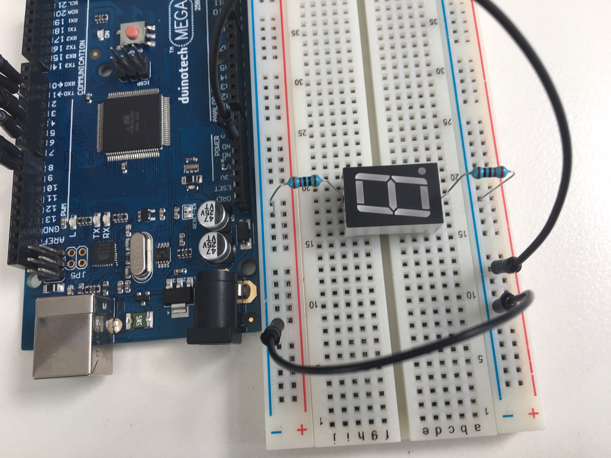
STEP 3
- Connect the two resistors. Pin 3 & Pin 8 on the display module both need a current limiter resistor to connect them to the -ve rail.
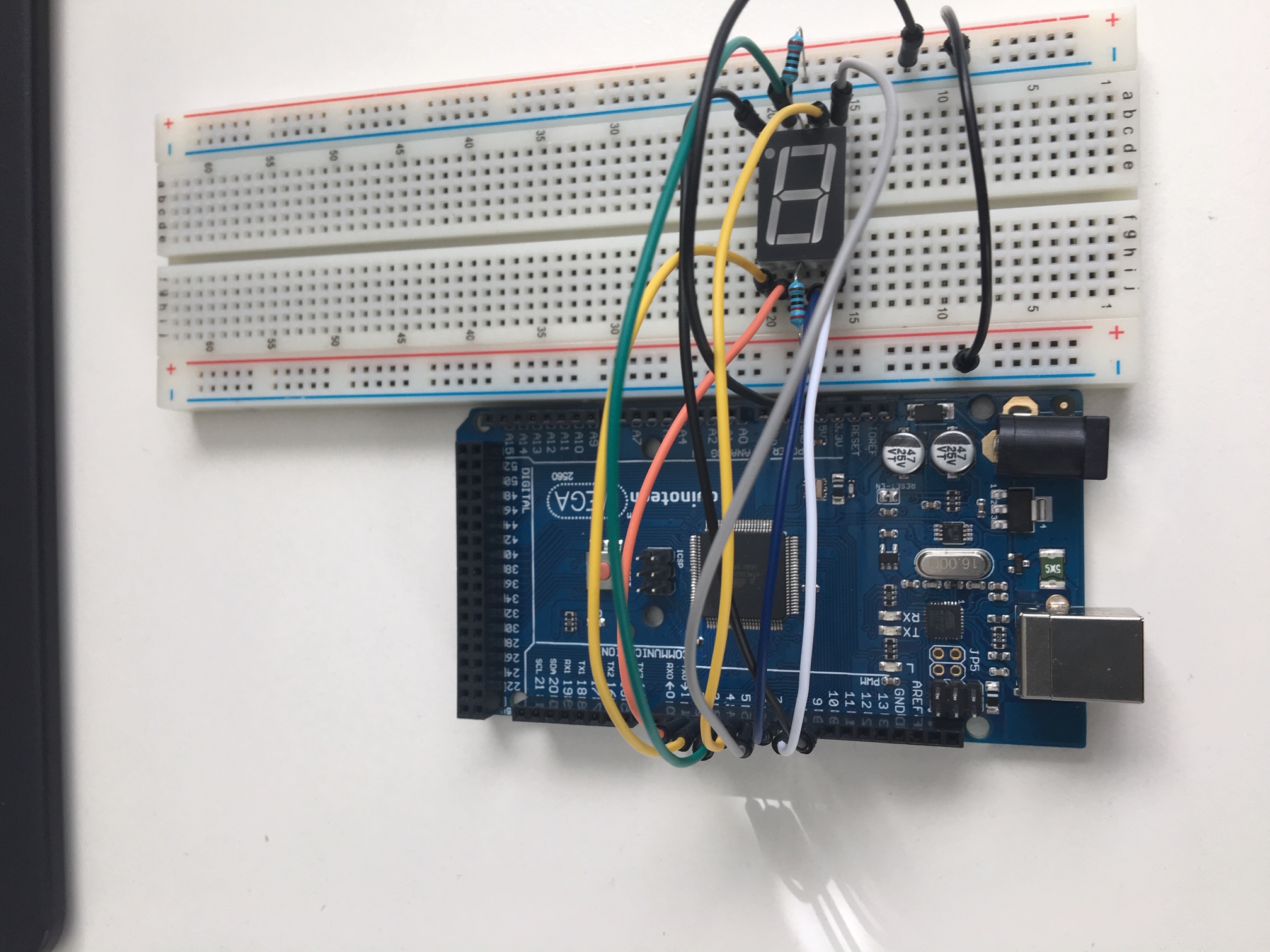
STEP 4
- Use jumper leads to connect the pins of the display module to the appropriate pins on the Duinotech Mega board
- Columns a to e within any row are internally connected, columns f to j within any row are also internally connected so you can use adjacent holes within these rows.
Module pin → Duinotech Mega board pin
5 (DP) → 9
10 (G) → 8
9 (F) → 7
1 (E) → 6
2 (D) → 5
4 (C) → 4
6 (B) → 3
7 (A) → 2
(3 & 8 (Gnd) → -ve rail)
STEP 5
- Open the Arduino IDE
- Clear the Arduino screen and then copy and paste this code into Arduino
__________________________________________________________________________________________________________________________________
int pinA = 2;
int pinB = 3;
int pinC = 4;
int pinD = 5;
int pinE = 6;
int pinF = 7;
int pinG = 8;
int pinDP = 9;
void setup() {
  // put your setup code here, to run once:
 pinMode(pinA,OUTPUT);
 pinMode(pinB,OUTPUT);
 pinMode(pinC,OUTPUT);
 pinMode(pinD,OUTPUT);
 pinMode(pinE,OUTPUT);
 pinMode(pinF,OUTPUT);
 pinMode(pinG,OUTPUT);
 pinMode(pinDP,OUTPUT);
}

void loop() {
  // The Letter P
digitalWrite(pinA,HIGH);
digitalWrite(pinB,HIGH);
digitalWrite(pinF,HIGH);
digitalWrite(pinG,HIGH);
digitalWrite(pinE,HIGH);
digitalWrite(pinDP,HIGH);
delay(1000);
digitalWrite(pinA,LOW);
digitalWrite(pinB,LOW);
digitalWrite(pinF,LOW);
digitalWrite(pinG,LOW);
digitalWrite(pinE,LOW);
digitalWrite(pinDP,LOW);
delay(1000);

// The Letter C
digitalWrite(pinA,HIGH);
digitalWrite(pinD,HIGH);
digitalWrite(pinF,HIGH);
digitalWrite(pinE,HIGH);
digitalWrite(pinDP,HIGH);
delay(1000);
digitalWrite(pinA,LOW);
digitalWrite(pinD,LOW);
digitalWrite(pinF,LOW);
digitalWrite(pinE,LOW);
digitalWrite(pinDP,LOW);
delay(1000);
}
__________________________________________________________________________________________________________________________________
- Connect the Duinotech Mega board to your computer with the USB cable.
- Save your file, (use a meaningful name).
- Click the √ icon to verify your code is correct. If no errors, then:
- Click the → icon to upload your code to the board
STEP 6
If you’ve been successful, you will see the letters "P" and "C" flashing on the seven segment module. It should look like the video below:
Put comments in your program that explain the different functions of the code. SAVE your file!
Use your knowledge of the segment pin locations to modify the code and change the pattern that flashes.
Can you change the code to flash different letters or some numbers?