How loops can help you
In ‘programming speak’ a LOOP is code that allows you to automate a repetitious task. It does require you to explicitly state a start condition and a stop condition, otherwise your program could get bogged down trying to do the loop forever & ever, (and never move on to do the rest of the program).
Connect 10 LEDs to your board, declare them all as outputs and switch them on one after the other.
Without loops your code would look something like this:
_____________________________________________________________________________________________________________________________________________________________
/*
 Blink 10 LEDs, one after the other, without using loops
 */

// Declare and initialise the LEDs on the pins where they are connected

int LED1 = 3;
int LED2 = 4;
int LED3 = 5;
int LED4 = 6;
int LED5 = 7;
int LED6 = 8;
int LED7 = 9;
int LED8 = 10;
int LED9 = 11;
int LED10 =12;

void setup() {
// put your setup code here, to run once:
// Declare all the LEDs as OUTPUT

pinMODE(LED1,OUTPUT);
pinMODE(LED2,OUTPUT);
pinMODE(LED3,OUTPUT);
pinMODE(LED4,OUTPUT);
pinMODE(LED5,OUTPUT);
pinMODE(LED6,OUTPUT);
pinMODE(LED7,OUTPUT);
pinMODE(LED8,OUTPUT);
pinMODE(LED9,OUTPUT);
pinMODE(LED10,OUTPUT);

}

void loop() {
  // put your main code here, to run repeatedly:
//  Now switch them all on, one after the other
digitalWrite (LED1, HIGH);  // switch the first one on
delay (1000);   // wait for one second
digitalWrite(LED2, HIGH);  // switch the second one on
delay(1000);    // wait for one second  etc...
digitalWrite (LED3, HIGH);
delay (1000);
digitalWrite (LED4, HIGH);
delay (1000);
digitalWrite (LED5, HIGH);
delay (1000);
digitalWrite (LED6, HIGH);
delay (1000);
digitalWrite (LED7, HIGH);
delay (1000);
digitalWrite (LED8, HIGH);
delay (1000);
digitalWrite (LED9, HIGH);
delay (1000);
digitalWrite (LED10, HIGH);
delay (1000);
//   Now switch them all off, one after the other
digitalWrite (LED1, LOW);  // switch the first one off
delay (1000);   // wait for one second
digitalWrite(LED2, LOW);  // switch the second one off
delay(1000);    // wait for one second  etc...
digitalWrite (LED3, LOW);
delay (1000);
digitalWrite (LED4, LOW);
delay (1000);
digitalWrite (LED5, LOW);
delay (1000);
digitalWrite (LED6, LOW);
delay (1000);
digitalWrite (LED7, LOW);
delay (1000);
digitalWrite (LED8, LOW);
delay (1000);
digitalWrite (LED9, LOW);
delay (1000);
digitalWrite (LED10, LOW);
delay (1000);

}
_____________________________________________________________________________________________________________________________________________________________
_____________________________________________________________________________________________________________________________________________________________
With loops, your code would look something like this:
_____________________________________________________________________________________________________________________________________________________________
/*
 Blink 10 LEDs, one after the other, without using loops
 */

// Declare and initialise the LEDs

int NumberOfLEDs = 10;  // we are going to attach 10 LEDs to our board
//  Use an arrray to hold the pin numbers that the LEDs are connected to.
//  The square brackets [] after the variable name (LEDPins) declares the variable as
//  an array, which means having one  OR MORE  values assigned to it
int LEDPins[] = {3,4,5,6,7,8,9,10,11,12};  // same 10 pins as before
int LEDDelay = 500; // half second pause between each on or off

void setup() {
  // use a for loop to initialize each pin as an output:
  // thisPin is a local variable, it only exists in this loop
  // we only need to declare it where it is being
  for (int thisPin = 3; thisPin < 13; thisPin++) {
    pinMode(thisPin, OUTPUT);
  }
}


void loop() {
// put your main code here, to run repeatedly:

//  Now switch them all on, one after the other, using valid start and stop conditions
for (int thisLED = 0; thisLED < NumberOfLEDs ; thisLED++){
digitalWrite (LEDPins[thisLED], HIGH);
delay (LEDDelay);
}

//   Now switch them all off, one after the other
for (int thisLED = 0; thisLED < NumberOfLEDs ; thisLED++){
digitalWrite (LEDPins[thisLED], LOW);
delay (250); }
}
_____________________________________________________________________________________________________________________________________________________________
______________________________________________________________________________________________________________________________________________________________
What the "for" loops actually do
 for (int thisPin = 3; thisPin < 13; thisPin++) {
    pinMode(thisPin, OUTPUT);
  }
This declares all the pins used as output. The first pin used on the Arduino board is pin 3, therefore we start by setting the local variable ‘thisPin’ to this value with the declaration: int thisPin = 3
This also is the condition that needs to be met to begin the loop.
The next part of the loop is the condition that tells the loop when to stop repeating: thisPin < 13
The value 13 is used because we are using pins 3 to 12, so when the variable thisPin is greater than 13, the condition is FALSE, and the loop will end (loops run while a required condition is TRUE).
The final part of the loop is the counter. Every time the loop is cycled through, the counter is incremented by one count. In Arduino, the double plus sign (++) is an instruction to add one. The double minus sign ( --) is an instruction to subtract one when you are doing a count-down).
The instruction that gets actioned every time the loop is cycled through is:
{ pinMode(thisPin, OUTPUT); }
Notice it is contained within a set of curly brackets that start directly after the "for" loop declaration and therefore belongs to the "for" loop. It will set each pin from 3 to 12 as an output.
If you want to try this for yourself, watch the videos and copy the code above into Arduino.
Wiring the Duintotech Mega board is straightforward:
Equipment:
1 x Breadboard
21 x wires
10 x LEDs
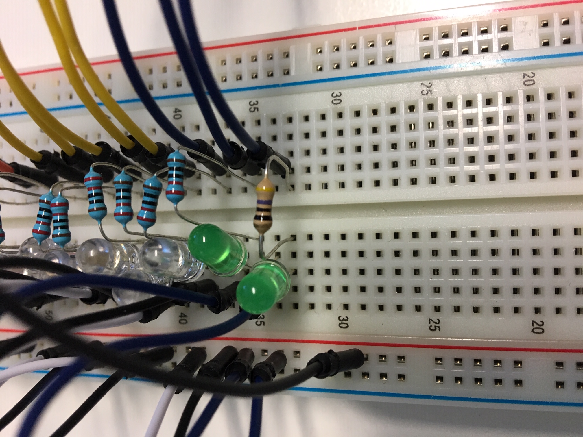
10 x 220 Ω resistors ( I only had 8 at the time, so I used a couple of 470 Ω to make up the numbers, that’s why some are a different colour)
1 x Duinotech Mega board
1 x USB cable
Step A. Attach 10 wires into pins 3 to 12 on the board
Step B. Plug the other ends of the wires into the breadboard, making sure they are all in different rows and at least one space between them. The example in the video has all these wires plugged in D column and rows 32 to 51
(Breadboard protocol for this: The columns are labelled alphabetically; the ROWS are labelled numerically)
Step C. Connect the current limiting resistors. Ensure both legs of each resistor stay in the same row as each wire on the breadboard.
Step D. Connect the LEDs. Make sure the positive leg goes in the same row as the resistor legs. [RECALL: The positive leg is the longer leg]
Step E. Connect 10 wires from the rows that the negative legs are in, to the positive rail on the breadboard
Step F. Connect one (longer) wire from the positive rail of the breadboard to one of the ground pins on the Duintotech Mega board
Step G. Verify and upload the code
Can you change the order and sequencing of the LEDs flashing?