Special | A | B | C | D | E | F | G | H | I | J | K | L | M | N | O | P | Q | R | S | T | U | V | W | X | Y | Z | ALL
S |
|---|
Safe programming languages | ||||||||||||||||||||
|---|---|---|---|---|---|---|---|---|---|---|---|---|---|---|---|---|---|---|---|---|
A safe programming language is one that is memory-safe (see Definition 1), type-safe (see Definition 2) and thread-safe (see Definition 3). Definition 1: Memory safety [WWK+21]
Assurance that adversaries cannot read or write to memory locations other than those intended by the programmer. A significant percentage of software vulnerabilities have been attributed to memory safety issues [NSA22], hence memory safety is of critical importance. Examples of violations of memory safety can be found in the discussion of common weakness CWE-787 and CWE-125. Definition 2: Type safety [Fru07, Sec. 1.1]
Type safety is a formal guarantee that the execution of any program is free of type errors, which are undesirable program behaviours resulting from attempts to perform on some value an operation that is inappropriate to the type of the value. For example, applying a factorial function to any value that is not an integer should result in a type error. Type safety ⇒ memory safety, but the converse is not true [SM07, Sec. 6.5.2], hence type safety is commonly considered to be a central theme in language-based security [Fru07]. Type-safe programming languages, e.g., Java , Ruby, C#, Go, Kotlin, Swift and Rust, have been around for a while. However, memory-unsafe languages are still being used because:
Nevertheless, adoption of type-safe languages, especially Rust, has been on the rise [Cla23]. Thread safety rounds up the desirable properties of type-safe languages. Definition 3: Thread safety [Ora19, Ch. 7]
The avoidance of data races, which occur when data are set to either correct or incorrect values, depending upon the order in which multiple threads access and modify the data. Watch the following LinkedIn Learning video about thread safety: Thread safety from IoT Foundations: Operating Systems Fundamentals by Ryan Hu Rust is an example of a type-safe language that is also thread-safe. References
| ||||||||||||||||||||
Satellite frequency bands | ||||||
|---|---|---|---|---|---|---|
Fig. 1 depicts the usage of different frequency bands. IEEE Standard 512 [IEE20] defines the letters designating the frequency bands. According to ESA, the main satellite frequency bands range from L to Ka; see also the same link for discussion of different usage of the frequency bands. References
| ||||||
Scan flip-flop and scan chain | ||||||||
|---|---|---|---|---|---|---|---|---|
The increasing usage of cutting-edge technologies in safety-critical applications leads to strict requirements on the detection of defects both at the end of manufacturing and in the field [VDSDN+19]. This gives birth to the design-for-testability (DFT) paradigm, which necessitates additional test circuits to be implemented on a system to 1️⃣ provide access to internal circuit elements, and thereby 2️⃣ provide enhanced controllability and observability of these elements [BT19, Sec. 4.7.1]. Scan is the most popular DFT technique [BT19, Sec. 3.7.2].
A scan chain is a chain of SFFs [BT19, Sec. 3.7.2.2]; see Fig. 2. When Test Enable (TE) is high, the scan chain works in test/shift mode [BT19, Sec. 3.7.2.2; VDSDN+19, p. 95].
Multiple scan chains are often used to reduce the time to load and observe. The integrity of a scan chain should be tested prior to application of a scan test sequence. For more information, see the attachment. References
| ||||||||
Security definitions/notions for encryption | |||
|---|---|---|---|
See 👇 attachment.
| |||
Side-channel attacks | ||||||||||||||
|---|---|---|---|---|---|---|---|---|---|---|---|---|---|---|
There is a bewildering array of side-channel attacks (see Definition 1). Definition 1: Side-channel attack [GGF17]
An attack enabled by leakage of information through timing, power consumption, electromagnetic, acoustic and other emissions from a physical system. It is not an understatement saying that the diversity of side-channel attacks is only limited by the creativity of humankind. A classic side-channel attack is differential power analysis (🖱 click for in-depth discussion). Meltdown and Spectre are high-profile side-channel attacks of recent years that exploit the hardware weakness CWE-1037. Below, we cover two recent attacks that are not as “classic” or “high-profile” but no less interesting. Example 1
In cybersecurity, the term “air gap” refers to an interface between two systems at which (a) they are not connected physically and (b) any logical connection is not automated (i.e., data is transferred through the interface only manually, under human control) [Shi07].
Just like physical insulation can be overcome, so can cyber insulation be. There is a group of researchers at the Ben-Gurion University of the Negev, including Mordechai Guri in the video below, that specialise in side-channel attacks, especially attacks that overcome air gaps. Watch Mordechai Guri’s Black Hat 2018 talk about “air-gap jumpers”: Among the air-gap side-channel attacks investigated so far are PowerHammer [GZBE20], named after the infamous rowhammer attack.
How PowerHammer works in a nutshell:
Example 2
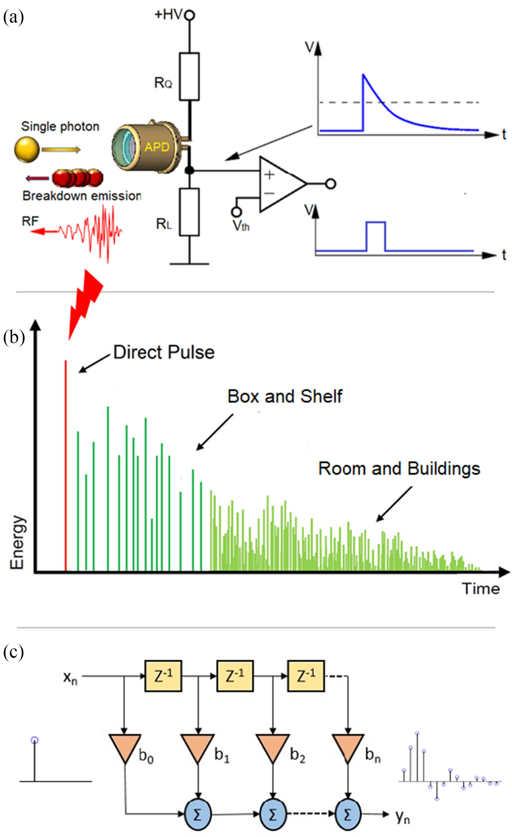
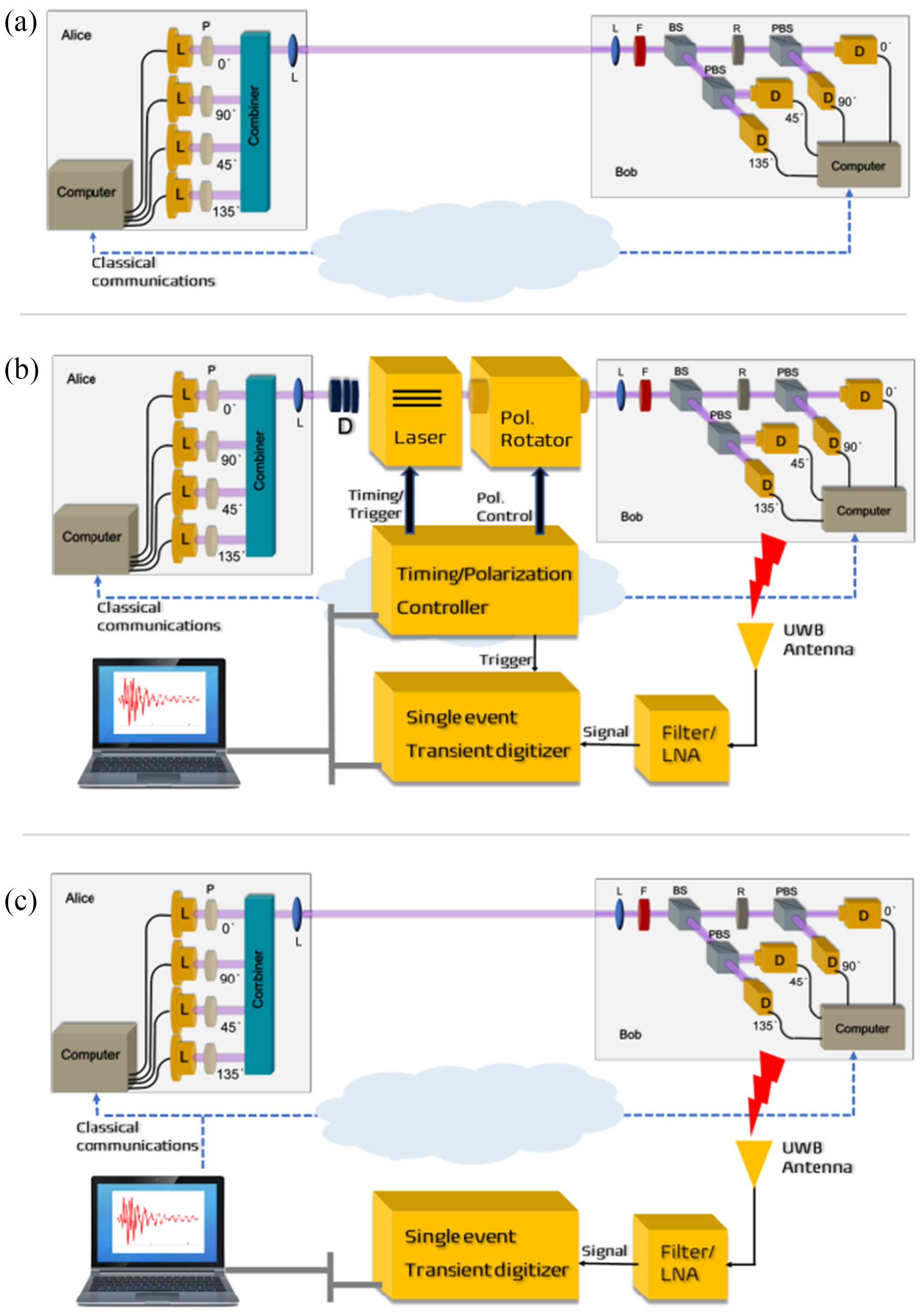
Quantum key distribution (QKD) is a method for generating and distributing symmetric cryptographic keys with information-theoretic security based on quantum information theory [ETS18]. The earliest QKD protocol is due to Bennett and Brassad [BB84] and is called BB84, named after the authors and the year it was proposed. BB84 encodes a classic bit in the polarisation state of a photon, which is a discrete variable, hence BB84 is an example of a discrete-variable quantum key distribution (DV-QKD) scheme. In a typical implementation of BB84, Bob uses single-photon detectors (see sample commercial products from ID Quantique SA) to receive photons from Alice, but this single-photon detector can be an Archilles’ heel of the DV-QKD system, as Durak et al. [DJK22] have shown. Among the most commonly used single-photon detectors are avalanche photodiodes (APDs), which are photodiodes with internal gain produced by the application of a reverse voltage.
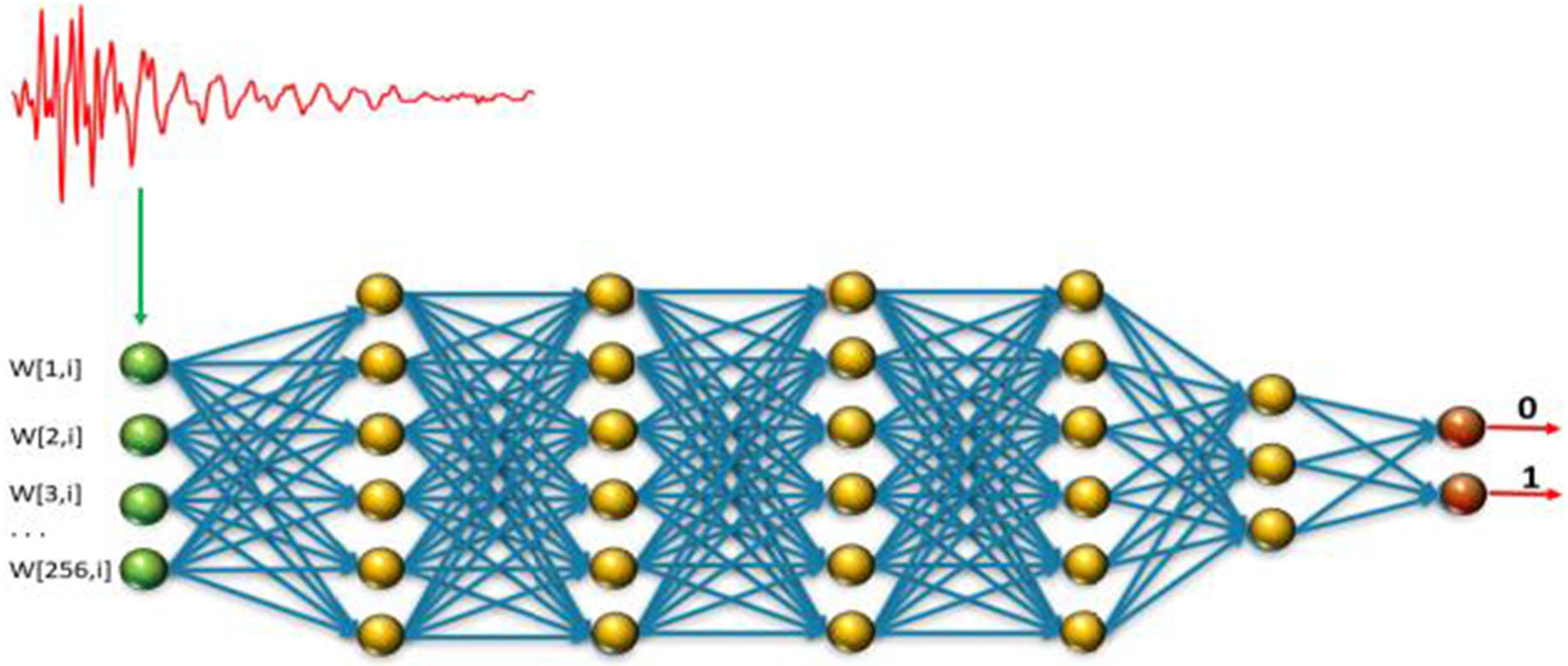
Fig. 6(b) and Fig. 7 show an experimental setup an attacker can use to gather FIR data, and train a neural network for classifying received RF emission into four polarisation states. The neural network in Fig. 8 takes a time-domain sample of 256 data points, and can be trained to classify a test sample into one of four polarisation states at high accuracy. Durak et al.’s [DJK22] results demonstrate feasibility of “cloning” Bob’s qubits using an RF side channel. CountermeasuresThe countermeasures for CWE-1300 apply. References
| ||||||||||||||
Solar System Internetwork (SSI) | ||||||||||||||||||||||||
|---|---|---|---|---|---|---|---|---|---|---|---|---|---|---|---|---|---|---|---|---|---|---|---|---|
The discussion below provides some historical context, an overview and a description of the network protocol stack of the Solar System Internetwork (SSI). HistoryIn 1999, the Interagency Operations Advisory Group (IOAG) was established to achieve cross support across the international space community and to expand the enabling levels of space communications and navigation interoperability [CCS14, Foreword]. In 2007, the IOAG chartered a Space Internetworking Strategy Group (SISG) to reach international consensus on a recommended approach for transitioning the participating agencies towards a future network-centric era of space mission operations [CCS14, Foreword]. In 2008, the SISG released a preliminary report on their operations concept for a Solar System Internetwork (SSI) [CCS14, Foreword]; see the 2011 conference version of the report [EDB11]. In 2010, the IOAG finalised the SSI Operations Concept and asked the Consultative Committee for Space Data Systems (CCSDS) to create the SSI architectural definition [CCS14, Foreword]. In 2014, the CCSDS Space Internetworking Services - Delay-Tolerant Networking (SIS-DTN) working group released the official informational report [CCS14]. The SSI architecture is based on international standards and voluntary agreements [CCS14, Executive Summary]. Participation in the SSI is expected to be incremental, and furthermore, the SSI specification and technologies are still evolving. In fact, the Interplanetary Networking Special Interest Group (IPNSIG), a chapter of the Internet Society, has the vision to develop a secure and robust Solar System Internet, by extending networking to space, from the historical point-to-point, “bent pipe” communication architecture to a store-and-forward, packet-switched design, interconnecting any number of terrestrial and space-borne nodes [KCB+21]. OverviewThe fundamental objective of the SSI is to provide automated and internetworked data communication services for space ventures (at least across the solar system) [CCS14, Executive Summary; EDB11, Sec. 2]. The emphasis on automation arises from the need to support communication among the various participants operating in space ventures without requiring a detailed understanding of space communication operations [CCS14, Executive Summary]. Examples of participants include [CCS14, Sec. 2.1]:
The SSI interconnects multiple networks built on two types of networking architectures, namely 1️⃣ the Internet architecture and 2️⃣ the DTN architecture. Fig. 1 depicts a communication scenario that the SSI architecture is designed to support. In Fig. 1,
To accommodate the multi-agency, multi-mission scenario in Fig. 1, the SSI architecture specifies three stages of functionality:
Protocol stackThe SSI protocol stack is a combination of the Internet Protocol (IP) stack and the Delay-Tolerant Network (DTN) protocol stack, as shown in Fig. 2. Going top-down along the DTN “facet” (CCSDS term) [CCS14, Sec. C3],
Fig. 3: A sample instantiation of the CCSDS protocol stack [CCS20d, Figure 2-1], where CLA = convergence layer adapter.
Fig. 5: DTN protocol building blocks in an end-to-end ABCBA view [CCS18, Figure 3-3]. In CCSDS terminology [CCS15b, Sec. 1.6.1], an ABCBA view/configuration refers to a multi-hop space communications configuration involving 1️⃣ multiple space and ground elements and 2️⃣ multiple direct earth-space and space-space links. ABCBA configurations nominally include elements from three or more agencies.
References
| ||||||||||||||||||||||||
Solar System Internetwork (SSI) Stage 1 Mission Functionality | |||
|---|---|---|---|
This continues from Solar System Internetwork (SSI). The Stage 1 Mission Functionality of the Solar System Internetwork (SSI) is the automation of basic communication processes between vehicles and Mission Operations Centers (MOCs) that might be performed for a single space flight mission, including [CCS14, Sec. 3]:
Fig. 1 depicts a sample communication scenario between two SSI nodes: one onboard the spacecraft and another at the spacecraft MOC.
The network configuration in Fig. 1 can be extended by setting up a separate SSI node for use by the instrument MOC, enabling the instrument MOC to operate on native instrument data flows securely routed through the node at the spacecraft MOC. Prerequisites and protocolsTo be part of the SSI, each node must be configured to run the Bundle Protocol (BP), i.e., a Bundle Protocol Agent (BPA) must be deployed at each node. For each node on the Earth surface, a Convergence-Layer Adapter (CLA) must be deployed underneath BP, enabling the node to communicate with other Earth-bound nodes via the Internet. For interoperation with the Internet, the CLA can use the Transmission Control Protocol (TCP) and User Datagram Protocol (UDP), or potentially the Licklider Transmission Protocol (LTP) running on top of UDP/Internet Protocol (IP). References | |||
Space Attack Research and Tactic Analysis (SPARTA) | ||||||||||||||||||||||||||
|---|---|---|---|---|---|---|---|---|---|---|---|---|---|---|---|---|---|---|---|---|---|---|---|---|---|---|
The Aerospace Corporation created the Space Attack Research and Tactic Analysis (SPARTA) cybersecurity matrix
The SPARTA matrix is a specialisation of the MITRE ATT&CK matrix for defining and categorising commonly identified activities that contribute to spacecraft compromises. The nine SPARTA tactics shown in the top row of Fig. 1 are a subset of the tactics in MITRE ATT&CK. Under each SPARTA tactic in Fig. 1, each of the main techniques accompanied by a double vertical sign, namely ⏸, can be divided into sub-techniques. For example, under tactic “Reconnaissance” (ST0001), the technique “Gather Spacecraft Design Information” (REC-0001) can be divided into 1️⃣ Software (REC-0001.01), 2️⃣ Firmware (REC-0001.02), 3️⃣ Cryptographic Algorithms (REC-0001.03), 4️⃣ Data Bus (REC-0001.04), 5️⃣ Thermal Control System (REC-0001.05), 6️⃣ Manoeuvre and Control (REC-0001.06), 7️⃣ Payload (REC-0001.07), 8️⃣ Power (REC-0001.08), and 9️⃣ Fault Management (REC-0001.09). Example 1: Payload
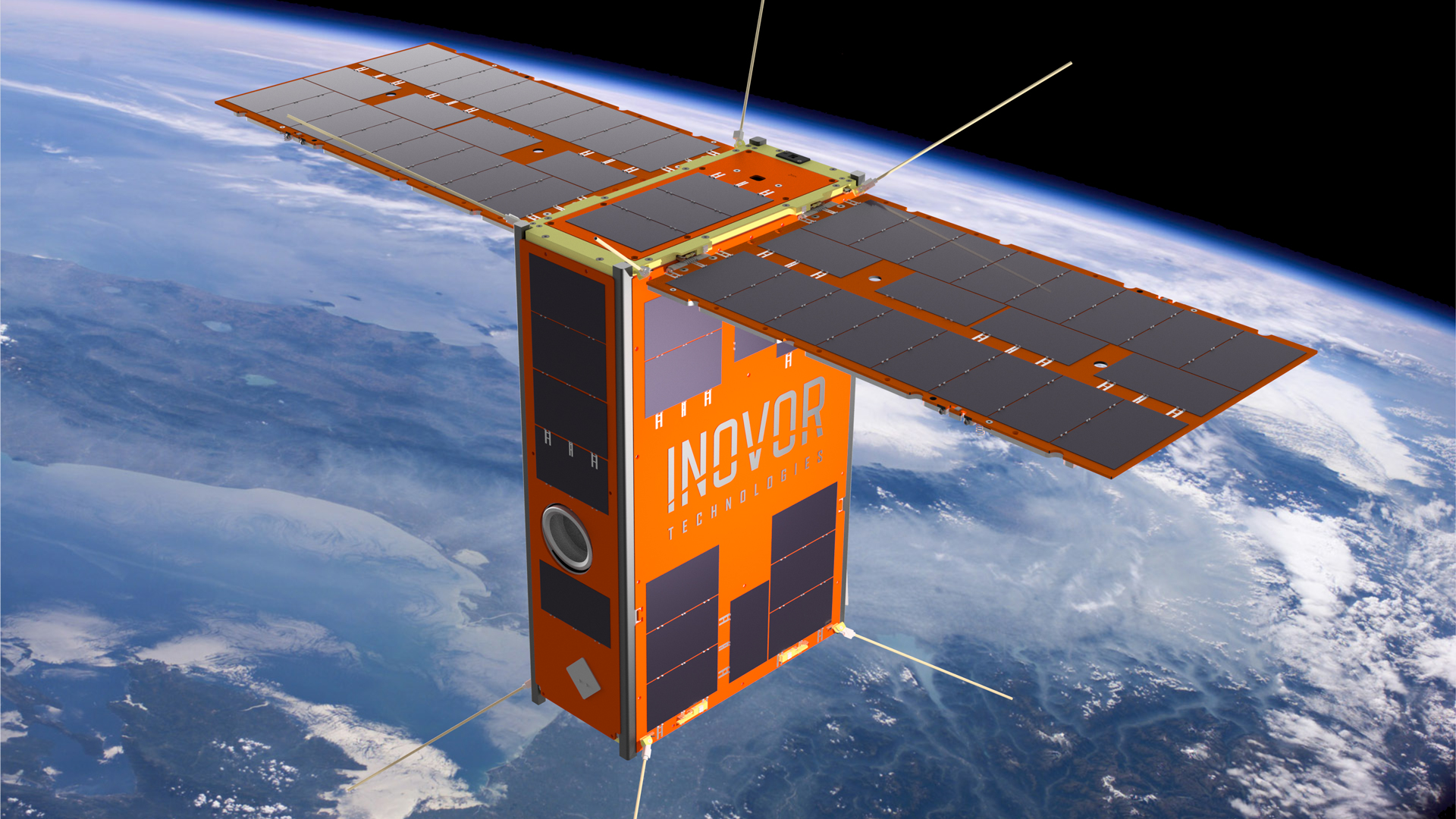
The South Australian 6U CubeSat Kanyini has two payloads: 1️⃣ a hyperspectral imager called HyperScout 2 for earth observation, and 2️⃣ an Internet-of-Things communications module. Example 2: Applying SPARTA to modelling a recent cyber attack
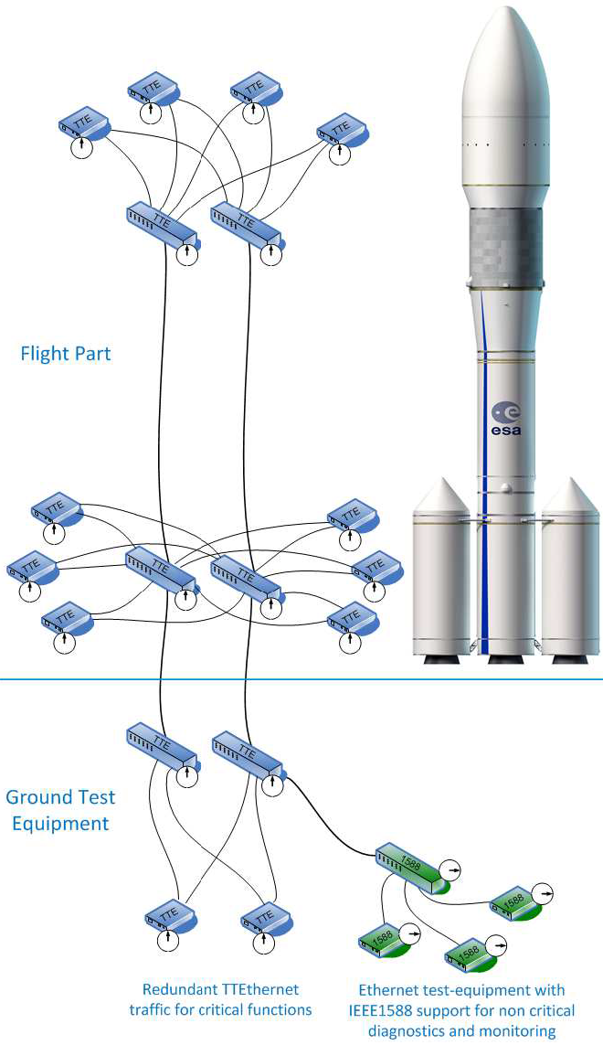
Watch a quick overview of the attack called PCspooF: A mixed-criticality system (MCS) is an embedded computing platform in which application functions of different criticalities share computation and/or communication resources [EDN16]. A mixed time-criticality system is an MCS where the criticality is messaging timeliness. Time-Triggered Ethernet (TTEthernet), as standardised in SAE AS6802, defines algorithms for clock synchronisation, clique detection, startup, and restart for switches and end systems to achieve fault-tolerant synchronisation in an Ethernet-based (IEEE 802.3) mixed time-criticality system. TTEthernet is used in avionics, industrial control systems (including those for power systems) and automotive systems [LPDK23], so any security vulnerability in TTEthernet would have wide-reaching consequences.
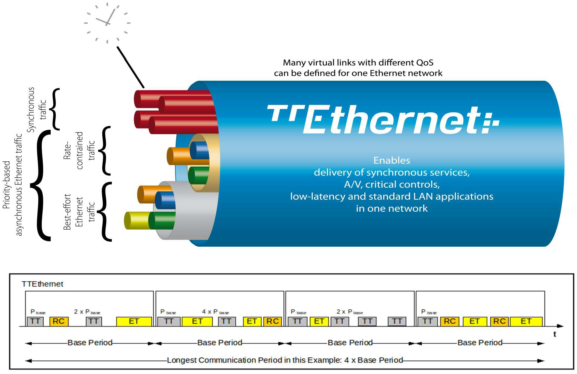
How TTEthernet works [LPDK23] A TTEthernet network contains two types of devices: switches and end systems. Fault-tolerance is enabled by network redundancy, and each redundant network is called a plane; Fig. 2 shows an example of a system using two planes. Time-triggered (TT) design = All TTEthernet devices are tightly synchronised and the behaviour of the network is determined by a global schedule made offline and loaded onto each TTEthernet device before deployment. The global schedule specifies when TT frames are forwarded and expected to arrive. The latency and jitter of TT traffic can be reduced to below 13 μs and 1 μs respectively [Fid15, slide 12]. TTEthernet also carries best-effort (BE, i.e., regular) Ethernet traffic and rate-constrained Avionics Full Duplex Switched Ethernet (AFDX, as standardised in ARINC Specification 664 P7-1) traffic; see Fig. 3. TTEthernet switches forward BE traffic around the pre-scheduled TT traffic when bandwidth permits. Mechanisms exist to isolate TT traffic from BE traffic, e.g.,
Central to TTEthernet is a synchronisation protocol, in which a device can participate as 1️⃣ a sync master, 2️⃣ a compression master, or 3️⃣ a sync client.
Devices exchange protocol control frames (PCFs) every integration cycle.
Receiving certain PCFs from a compression master can cause sync masters and clients to lose synchronisation.
Attacker/threat model for PCspooF The PCspooF attack is feasible provided:
The PCspooF attack PCspooF is a cyber-physical attack that attempts to disrupt the TTEthernet synchronisation protocol by spoofing PCFs, and thereby inflict denial of service on its victim. The attack happens in two stages:
Applying SPARTA Using the language of SPARTA, these attack stages can be identified [The22]: 1️⃣ Reconnaissance, 2️⃣ Resource Development, 3️⃣ Initial Access, 4️⃣ Execution, 5️⃣ Lateral Movement, 6️⃣ Impact Table 1 and Table 2 map these attack stages to the attack steps in PCspooF.
References
| ||||||||||||||||||||||||||
Space Packet Protocol (SPP) | ||||||||
|---|---|---|---|---|---|---|---|---|
IntroductionIn many space applications, it is desirable to have a single, common application-layer data structure for the creation, storage, and transport of variable-length application-layer data. These data is expected to be 1️⃣ exchanged and stored on board, 2️⃣ transferred over one or more space data links, and 3️⃣ used within ground systems. It is often necessary to identify the 1️⃣ type, 2️⃣ source, and/or 3️⃣ destination of these data. The preceding needs motivate the definition of the Space Packet Protocol (SPP). The SPP is designed as a self-delimited carrier of a data unit — called a Space Packet — that contains an application process identifier (APID) used to identify the data contents, data source, and/or data user within a given enterprise [CCS20d, Sec. 2.1.1]. Fig. 1 shows where the SPP sits in the CCSDS protocol stack. Fig. 2 shows a communication scenario between a spacecraft and a ground terminal, where the SPP plays an important role. Fig. 1: The SPP sits above the data link layer and below the upper layers in the CCSDS protocol stack [CCS20d, Figure 2-1], where CLA = convergence layer adapter. Fig. 2: A sample communication scenario [CCS20a, Figure 9-12], featuring mission operations (MO) applications residing in the spacecraft’s onboard computer (OBC). All OBC apps are under the control of a real-time operating system (RTOS); with the striped blocks running in hard real time. Science operations (SO) functions are executed through Message Transfer Service, File and Packet Store Services, etc. The yellow blocks represent the spacecraft onboard interface services (SOIS), and the SPP is one of these services. Between the SPP and the MO applications sits the Message Abstraction Layer (MAL) [CCS13a], an important component of CCSDS’s Missions Operations Framework. For applications on separate onboard computers, communications pass through the whole stack and use the physical subnetwork to communicate. For applications on the same computer, communications pass through the stack to a local loopback function in the software bus. APIDAPIDs are unique in a single naming domain [CCS20d, Sec. 2.1.3] An APID naming domain usually corresponds to a spacecraft, or an element of a constellation of space vehicles. Every space project allocates the APIDs to be used in a naming domain. More precisely, the space project assigns APIDs to managed data paths within a naming domain. Open-source implementationsThe following open-source implementations are known at the time of writing:
References
| ||||||||
Spectre attacks | ||||
|---|---|---|---|---|
The Spectre attacks exploit the weakness CWE-1037 “Processor Optimization Removal or Modification of Security-critical Code”. Modern processors use branch prediction and speculative execution to maximise performance, but the implementations of these optimisations in many processors were found to have broken a range of software security mechanisms, including operating system process separation, containerisation, just-in-time (JIT) compilation, and countermeasures to cache timing and side-channel attacks [KHF+20]. Watch the presentation given by one of the discoverers of Spectre attacks at the 40th IEEE Symposim on Security and Privacy: More information on the Meltdown and Spectre website. References
| ||||


