Special | A | B | C | D | E | F | G | H | I | J | K | L | M | N | O | P | Q | R | S | T | U | V | W | X | Y | Z | ALL
A |
|---|
AC-DC conversion | |||
|---|---|---|---|
Applications of control: examples | |||
|---|---|---|---|
See 👇 attachment.
| |||
Applications of power electronics: examples | ||||||||||||||||||||||||
|---|---|---|---|---|---|---|---|---|---|---|---|---|---|---|---|---|---|---|---|---|---|---|---|---|
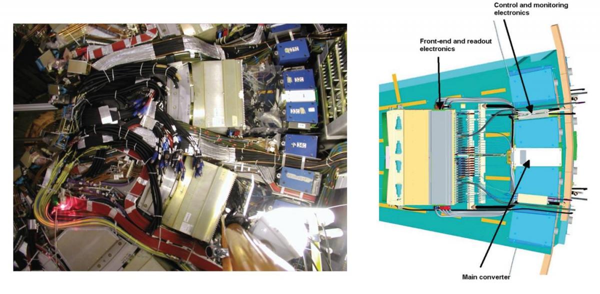
From the computer we are now using to the Internet-of-Things devices that increasingly permeate our everyday reality (see Fig. 1); from variable speed drives (see Fig. 2) to renewable energy systems (see Fig. 3); from automobiles (see [BM11, Ch. 4], [Bad13, Sec. 3.4], [Ras18, Ch. 32]) to aircraft (see [KE01, WB14, SM15]); from particle accelerators (see Fig. 4) to satellites (see Fig. 5), power electronics is everywhere. Wherever there is a need to electrically power a device or system in a certain way, there is a need for power electronics.  Fig. 2: A classic representative of an industrial power electronic system is a variable-speed drive (VSD) [Gey17, Ch. 1]. A well-known example of a medium-voltage VSD is ABB’s ACS 6000, as pictured above. A VSD enables the operation of an electrical machine at an adjustable speed and at an adjustable torque. This is achieved by decoupling the grid electrically from the machine. Such a system consists of a step-down transformer connected to the grid, a rectifier, a DC link, an inverter, and an electrical machine driving a mechanical load. The rectifier, which can be a diode rectifier or more commonly an active front end, converts the grid’s fixed-frequency AC quantities (at either 50 or 60 Hz) to DC quantities. The DC link serves as an energy storage element, and decouples the rectifier from the inverter. The inverter transforms the DC quantities back to AC at a variable frequency that is proportional to the rotational speed of the mechanical load.  Fig. 3: This example is about Kakosimos et al.’s highly cited work [KKM13] on maximum power point tracking (MPPT). MPPT refers to the tracking of the maximum power point on the current-voltage curve associated with a photovoltaic (PV) system in order to extract maximum power from said system. Kakosimos et al. designed and developed an MPPT controller for the boost converter at the output of the solar panels. Above, (a) shows the system setup, (b) shows the solar panels, (c) shows the boost converter hardware, and (d) shows the boost converter schematics in relation to the controller running on a TMS320F2812 Digital Signal Processor [KKM13, Figures 13-14]. 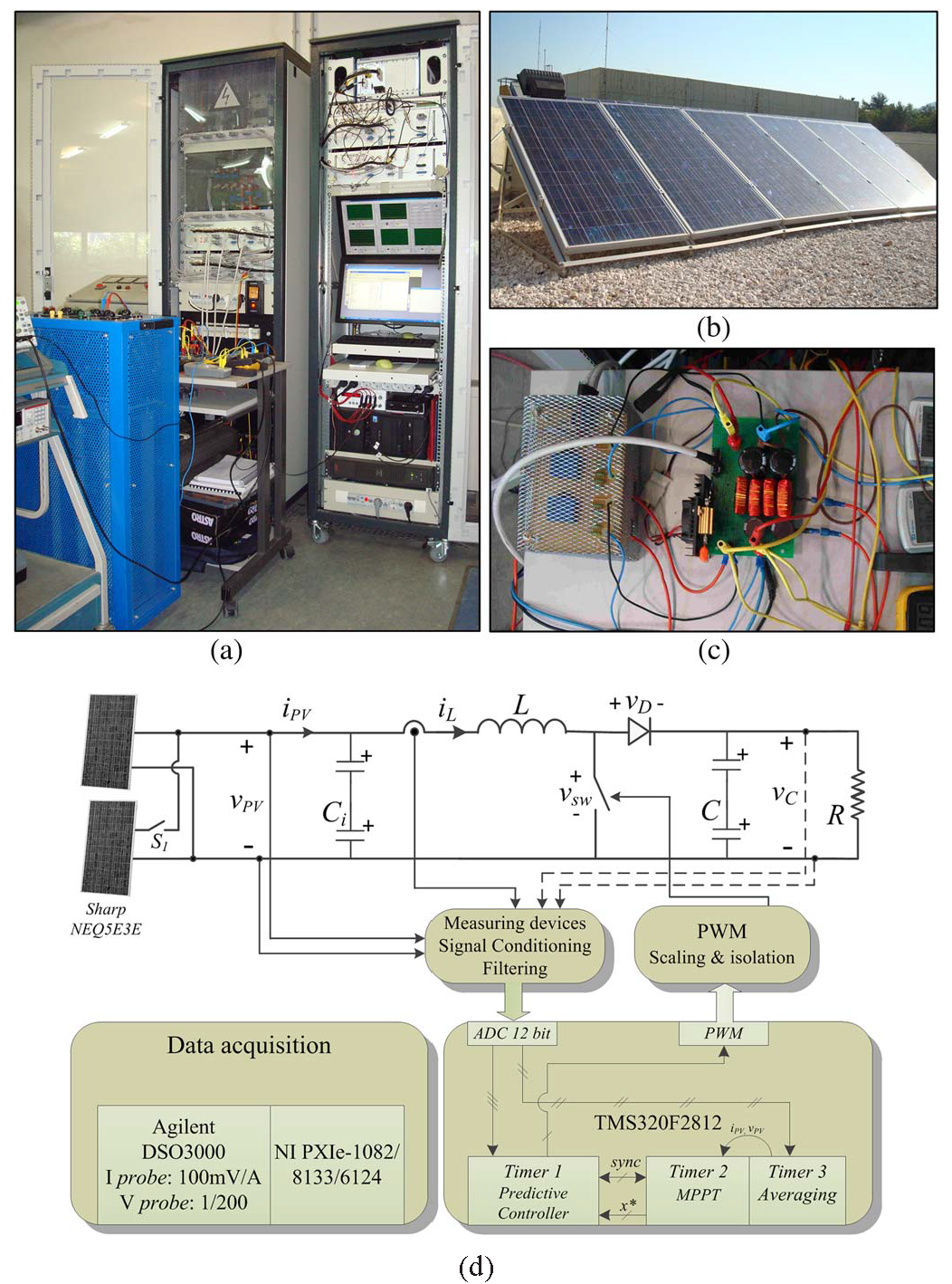 Fig. 4: In high-energy physics experiments, the search for physically significant particle generation/disintegration events requires the capability of 1️⃣ detecting particle trajectories in real time, 2️⃣ applying predefined selection criteria to identify events of interest, and 3️⃣ storing all data related to the identified events of interest. This capability imposes stringent performance requirements on the sensors and associated signal processing and control electronics. The operational frequency of these electronics depends on the event generation rate, which can be as high as several tens of MHz. The requirements are so demanding that all these electronics have to be located inside the sensor array for tracking particle trajectories and measuring their energy. For large-scale experiments like the Large Hadron Collider experiments, the required number of sensors and associated electronic components is so large that it becomes impractical to supply power from outside the chamber through cables. The solution is point-of-load (POL) converters, i.e., DC-DC converters that are physically located as close as possible to their electrical load. This means the power supply circuits are located on the same boards where the signal processing and control electronics are located, i.e., inside the sensor array. The design of POL converters is challenging because of the size constraints and highly hostile environmental conditions (radiation, temperature, magnetic field) they operate in. 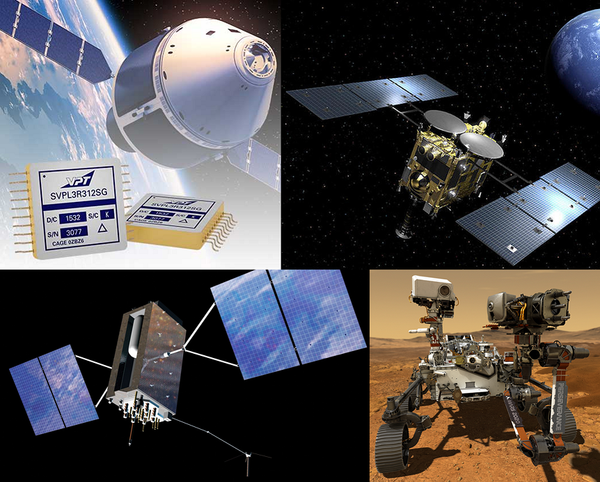 Applications of power electronics are too many to list exhaustively, but most textbooks provide a list — check the bibliography at the end of each lecture! Below, Table 1 has a list of applications taken from [Ras14, TABLE 1.1]. Those who are not content with Table 1 are encouraged to browse relevant journals, e.g.,
References
| ||||||||||||||||||||||||


C |
|---|
Common mode | ||||
|---|---|---|---|---|
There are two main types of electromagnetic interference (EMI), namely conducted emission and radiated emission. Conducted emission can further be classified into two types, namely differential-mode noise and common-mode noise, as shown in Fig. 1. 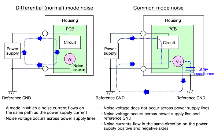 For differential-mode noise, the noise source appears across power supply lines and is in series with the power supply line. The noise current flows in the same direction as the power supply current. Noise is so-called “differential-mode” because the outgoing and return currents are oppositely directed. For common-mode noise, the noise current that has leaked via a stray capacitance or the like passes through ground and returns to the power supply line. A noise voltage does not appear across the power supply lines. Noise is so-called “common-mode” because the direction of the noise currents on the positive (+) and the negative (−) sides of the power supply have the same direction. References
| ||||
Control systems: introduction | ||
|---|---|---|
See 👇 attachment.
| ||
D |
|---|
DC-DC step-down / buck conversion | |||
|---|---|---|---|
See 👇 attachment.
| |||
DC-DC step-up / boost conversion and buck-boost conversion | |||
|---|---|---|---|
See 👇 attachment.
| |||
F |
|---|
Frequency response | ||
|---|---|---|
See 👇 attachment.
| ||
G |
|---|
Galvanic isolation | ||||||||||||||||||
|---|---|---|---|---|---|---|---|---|---|---|---|---|---|---|---|---|---|---|
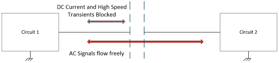
Those who have worked with high-voltage equipment before can readily appreciate the benefits of electrical isolation. When two devices or circuits are in communication, DC currents and AC signals typically flow freely. In low-voltage systems, this is a safe way for two parts of the system to work. However, when high voltage enters into one or more parts of the system, freely-flowing DC current and some AC signals can cause errors, physical damage, and/or create hazardous conditions of operation [Tex20a]. A solution to this problem is galvanic isolation: Definition 1: Galvanic isolation
A means of preventing DC and unwanted AC currents between two parts of a system while still allowing signal and power transfer between those two parts [Tex20a]. Alternative definitions:
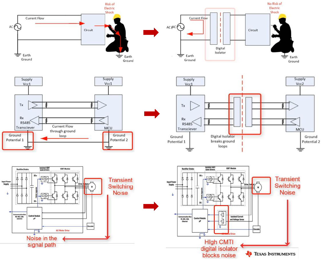
Galvanic isolation can help 1️⃣ protect human operators from electrical shocks, 2️⃣ prevent ground loops, and 3️⃣ improve noise immunity (and thus maintain signal integrity); see Fig. 1. Fig. 1: Sample applications of galvanic isolation. In Fig. 1,
Isolator devices are available in three primary technologies as shown in Fig. 2: 1️⃣ optical, 2️⃣ inductive, and 3️⃣ capacitive. 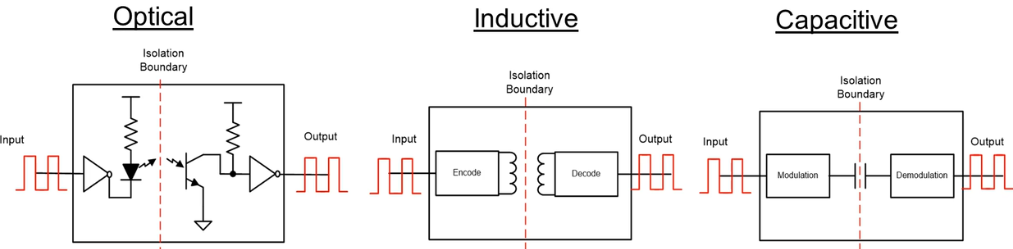 Each technology uses a different insulator material with different dielectric strengths.
Here is how the technologies compare [Sch17, Tex20a]: Optical isolators, also called opto-isolators or optocouplers, typically use air, epoxy or mold compound as the dielectric, which has a low dielectric strength. These isolators have high immunity to electrical and magnetic noise, but their communication rate is limited by LED switching speed. They also suffer from LED aging issues and higher power dissipation than other types of isolators. Inductive/magnetic isolators typically use polyimide as the dielectric, which has a moderate dielectric strength. These isolators enjoy a long lifetime, and their passive barrier can withstand surges/spikes much higher than their continuous voltage rating. However, their inductive coupling via magnetic fields renders them susceptible to magnetic interference. Nevertheless, some new designs manage to certifiably overcome this susceptibility in industry standard tests. Inductive isolation is the oldest among the three technologies. Capacitive isolators typically use SiO2 as the dielectric, which has a high dielectric strength. These isolators have high magnetic immunity, and can support a higher bandwidth than optical isolators. However, their usage of electric fields for data transmission renders them susceptible to electrical interference. Power converters are typically isolated using use either transformer or coupled inductor as shown in Fig. 3.  Besides galvanic isolation, the isolator also serve the purpose of voltage level shifting, or providing multiple outputs [Bla18, Sec. 1.1.1]. However, nonisolated converters are often preferred in applications where galvanic isolation is not a necessity, because they are less bulky, less costly, more efficient and more reliable. Example 1
Here is an example of an isolated DC-DC converter, the 700DNC40-12-xG, from Bel Power Solutions rated at 4 KW, suitable for use in hybrid and electric vehicles: The topic of galvanic isolation can easily occupy an entire course if we really go into the details, but please take advantage of Texas Instruments’ “Introduction to isolation” video series as well as Digi-Key Electronics’ resources [Sch17, Bak18, Pin20]. References
| ||||||||||||||||||

H |
|---|
Heuristic tuning of controllers | |||
|---|---|---|---|
See 👇 attachment.
| |||
K |
|---|
Kalman filter | |||
|---|---|---|---|
See 👇 attachment: 1️⃣ l_kf.pdf for an introduction to the Kalman filter, 2️⃣ l_derivekf.pdf for a derivation of the Kalman filter.
| |||
M |
|---|
Modelling of power-electronic circuits and controller design | |||
|---|---|---|---|
See 👇 attachment or the latest source on OneNote.
| |||
P |
|---|
PID control | |||
|---|---|---|---|
See 👇 attachment.
| |||
Power-electronic devices: overview | |||
|---|---|---|---|
See 👇 attachment or the latest source on Overleaf.
| |||
Power electronics: introduction | |||
|---|---|---|---|
See 👇 attachment or the latest source on Overleaf. See also overview of power-electronic devices. | |||
Power transistors | |||
|---|---|---|---|
See 👇 attachment or the latest source on Overleaf.
| |||
S |
|---|
Stability | |||
|---|---|---|---|
See 👇 attachment.
| |||
State-space equations | |||
|---|---|---|---|
See 👇 attachment.
| |||
System dynamics and modelling | |||
|---|---|---|---|
See 👇 attachment for modelling of linear system dynamics using differential equations, transfer functions and state-space equations. State-space equations are covered in more details in a separate knowledge base entry. Modelling of power-electronic circuits is covered in a separate knowledge base entry. | |||
T |
|---|
Thyristors | |||
|---|---|---|---|
See 👇 attachment.
| |||
Time response | |||
|---|---|---|---|
See 👇 attachment.
| |||