Special | A | B | C | D | E | F | G | H | I | J | K | L | M | N | O | P | Q | R | S | T | U | V | W | X | Y | Z | ALL
K |
|---|
Key establishment and key management | ||||||||||
|---|---|---|---|---|---|---|---|---|---|---|
Key establishment (see Definition 1) is part of key management (see Definition 2). Definition 1: Key establishment [MvV96, Definition 1.63]
A process whereby a shared secret key becomes available to two or more parties, for subsequent cryptographic use. Definition 2: Key management [BB19, p. 12]
Activities involved in the handling of cryptographic keys and other related parameters (e.g., IVs and domain parameters) during the entire life cycle of the keys, including their generation, storage, establishment, entry and output into cryptographic modules, use and destruction. Simply speaking, key management is a set of processes and mechanisms which support key establishment and the maintenance of ongoing keying relationships between parties, including replacing older keys with new keys as necessary [MvV96, Definition 1.64]; see Fig. 1.  Example 1
Key management includes identification of the key types. CCSDS [CCS11] has identified the following key types for securing space missions:
Key establishment can be broadly classified into key agreement (see Definition 3) and key transport (see Definition 4). Definition 3: Key agreement [BB19, p. 11]
A pair-wise key-establishment procedure in which the resultant secret keying material is a function of information contributed by both participants, so that neither party can predetermine the value of the secret keying material independently from the contributions of the other party. 👩 ➡ 🔑 ⬅ 🧔 Definition 4: Key transport [BB19, p. 14]
A key-establishment procedure whereby one entity (the sender) selects a value for secret keying material and then securely distributes that value to one or more other entities (the receivers). 👩 ➡ 🔑 ➡ 👨👩👧👦 Key agreement is more popular than key transport, and the de facto standard key agreement protocol is Diffie-Hellman key agreement. References
| ||||||||||
L |
|---|
Licklider Transmission Protocol (LTP) | ||||||||||
|---|---|---|---|---|---|---|---|---|---|---|
CCSDS has adopted the Licklider Transmission Protocol (LTP) as specified in the IETF RFC 5326 [BFR08b] and the associated security extensions specified in IETF RFC 5327 [BFR08a] to provide reliability and authentication mechanisms on top of an underlying (usually data link) communication service [CCS15b, Sec. 1.1]. In an Interplanetary Internet setting deploying the Bundle Protocol [BFR08b], LTP is intended to serve as a reliable “convergence layer” protocol operating in pairwise fashion between adjacent in-range Interplanetary Internet nodes. LTP aggregates multiple layer-(N+1) PDUs into a single layer-N PDU for reliable delivery — this allows the system to reduce the acknowledgement-channel bandwidth in the case that the layer-(N+1) (and higher) protocols transmit many small PDUs, each of which might otherwise require independent acknowledgement; see Fig. 1. In CCSDS settings [CCS15b, Sec. 1.2], LTP is intended for use over package delivery services including packet telecommand and packet telemetry. For space links, LTP is typically deployed over a CCSDS data link that supports CCSDS Encapsulation Packets so that one LPT segment can be encapsulated in a single Encapsulation Packet. LTP can also operate over ground-network services, in which case it is usually deployed over UDP; see Fig. 2. Fig. 1: To protocols above LTP (e.g., Bundle Protocol), LTP enables reliable delivery of layer-(N+1) PDUs across a link [CCS15b, Figure 1-1]. For LTP, the interface to the data link is via either direct encapsulation in CCSDS Space Packets or the CCSDS Encapsulation Service.   References
| ||||||||||
M |
|---|
Meltdown attacks | ||||||
|---|---|---|---|---|---|---|
Out-of-order execution is a prevalent performance feature of modern processors for reducing latencies of busy execution units, e.g., a memory fetch unit waiting for data from memory: instead of stalling execution, a processor skips ahead and executes subsequent instructions [LSG+18]. See Fig. 1. Fig. 1: If an executed instruction causes an exception that diverts the control flow to an exception handler, the subsequent instruction must not be executed [LSG+18, Figure 3]. Due to out-of-order execution, the subsequent instructions may already have been partially executed, but not retired. However, architectural effects of the execution are discarded.  Although the instructions executed out of order do not have any visible architectural effect on the registers or memory, they have microarchitectural side effects [LSG+18, Sec. 3].
Meltdown consists of two building blocks [LSG+18, Sec. 4], as illustrated in Fig. 2:
Operation-wise, Meltdown consists of 3 steps [LSG+18, Sec. 5.1]:
Fig. 2: The Meltdown attack uses exception handling or suppression, e.g., TSX (disabled by default since 2021), to run a series of transient instructions [LSG+18, Figure 5]. The covert channel consists of 1️⃣ transient instructions obtaining a (persistent) secret value and changing the microarchitectural state of the processor based on this secret value; 2️⃣ FLUSH+RELOAD reading the microarchitectural state, making it architectural and recovering the secret value.  Watch the presentation given by one of the discoverers of Meltdown attacks at the 27th USENIX Security Symposium: Since FLUSH+RELOAD was mentioned, watch the original presentation at USENIX Security ’14: More information on the Meltdown and Spectre website. References
| ||||||

MITRE ATLAS | ||||||||||
|---|---|---|---|---|---|---|---|---|---|---|
The field of adversarial machine learning (AML) is concerned with the study of attacks on machine learning (ML) algorithms and the design of robust ML algorithms to defend against these attacks [TBH+19, Sec. 1]. ML systems (and by extension AI systems) can fail in many ways, some more obvious than the others. AML is not about ML systems failing when they make wrong inferences; it is about ML systems being tricked into making wrong inferences. Consider three basic attack scenarios on ML systems: Black-box evasion attack: Consider the most common deployment scenario in Fig. 1, where an ML model is deployed as an API endpoint.
White-box evasion attack: Consider the scenario in Fig. 2, where an ML model exists on a smartphone or an IoT edge node, which an adversary has access to.
Poisoning attacks: Consider the scenario in Fig. 3, where an adversary has control over the training data, process and hence the model.
   Watch introduction to evasion attacks (informally called “perturbation attacks”) on LinkedIn Learning: Perturbation attacks and AUPs from Security Risks in AI and Machine Learning: Categorizing Attacks and Failure Modes by Diana Kelley Watch introduction to poisoning attacks on LinkedIn Learning: Poisoning attacks from Security Risks in AI and Machine Learning: Categorizing Attacks and Failure Modes by Diana Kelley In response to the threats of AML, in 2020, MITRE and Microsoft, released the Adversarial ML Threat Matrix in collaboration with Bosch, IBM, NVIDIA, Airbus, University of Toronto, etc. Subsequently, in 2021, more organisations joined MITRE and Microsoft to release Version 2.0, and renamed the matrix to MITRE ATLAS (Adversarial Threat Landscape for Artificial-Intelligence Systems). MITRE ATLAS is a knowledge base — modelled after MITRE ATT&CK — of adversary tactics, techniques, and case studies for ML systems based on real-world observations, demonstrations from ML red teams and security groups, and the state of the possible from academic research. Watch MITRE’s presentation: References
| ||||||||||

MITRE ATT&CK | ||||||||||||||||||||||||||||||||||||||||||||||||||||||||||||||||||||||||||||||||||||||||||
|---|---|---|---|---|---|---|---|---|---|---|---|---|---|---|---|---|---|---|---|---|---|---|---|---|---|---|---|---|---|---|---|---|---|---|---|---|---|---|---|---|---|---|---|---|---|---|---|---|---|---|---|---|---|---|---|---|---|---|---|---|---|---|---|---|---|---|---|---|---|---|---|---|---|---|---|---|---|---|---|---|---|---|---|---|---|---|---|---|---|---|
MITRE ATT&CK® is a knowledge base of adversary tactics (capturing “why”) and techniques (capturing “how”) based on real-world observations. There are three versions [SAM+20]: 1️⃣ Enterprise (first published in 2015), 2️⃣ Mobile (first published in 2017), and 3️⃣ Industrial Control System (ICS, first published in 2020). Fig. 1 below shows the fourteen MITRE ATT&CK Enterprise tactics: 
The Mobile tactics and ICS tactics are summarised below. Note a tactic in the Mobile context is not the same as the identically named tactic in the ICS context.
Among the tools that support the ATT&CK framework is MITRE CALDERA™ (source code on GitHub).
A (blurry) demo is available on YouTube: A complementary model to ATT&CK called PRE-ATT&CK was published in 2017 to focus on “left of exploit” behavior [SAM+20]:
ATT&CK is not meant to be exhaustive, because that is the role of MITRE Common Weakness Enumeration (CWE™) and MITRE Common Attack Pattern Enumeration and Classification (CAPEC™) [SAM+20].
References
| ||||||||||||||||||||||||||||||||||||||||||||||||||||||||||||||||||||||||||||||||||||||||||
MITRE CAPEC | |||
|---|---|---|---|
MITRE’s Common Attack Pattern Enumeration and Classification (CAPEC™) effort provides a publicly available catalogue of common attack patterns to help users understand how adversaries exploit weaknesses in applications and other cyber-enabled capabilities. Attack patterns are descriptions of the common attributes and approaches employed by adversaries to exploit known weaknesses in cyber-enabled capabilities.
As of writing, CAPEC stands at version 3.9 and contains 559 attack patterns. For example, CAPEC-98 is phishing: Definition 1: Phishing
A social engineering technique where an attacker masquerades as a legitimate entity with which the victim might interact (e.g., do business) in order to prompt the user to reveal some confidential information (typically authentication credentials) that can later be used by an attacker. CAPEC-98 can be mapped to CWE-451 “User Interface (UI) Misrepresentation of Critical Information”. | |||
MITRE D3FEND | ||||
|---|---|---|---|---|
MITRE D3FEND is a knowledge base — more precisely a knowledge graph — of cybersecurity countermeasures/techniques, created with the primary goal of helping standardise the vocabulary used to describe defensive cybersecurity functions/technologies.
The D3FEND knowledge graph was designed to map MITRE ATT&CK techniques (or sub-techniques) through digital artefacts to defensive techniques; see Fig. 1.
 Operationally speaking, the D3FEND knowledge graph allows looking up of defence techniques against specific MITRE ATT&CK techniques.
Watch an overview of the D3FEND knowledge graph from MITRE on YouTube: References
| ||||

MITRE Engage | ||||||||||||
|---|---|---|---|---|---|---|---|---|---|---|---|---|
MITRE Engage (previously MITRE Shield) is a framework for planning and discussing adversary engagement operations.
Cyber defense has traditionally focussed on applying defence-in-depth to deny adversaries’ access to an organisation’s critical cyber assets. Increasingly, actively engaging adversaries proves to be more effective defence [MIT22b].
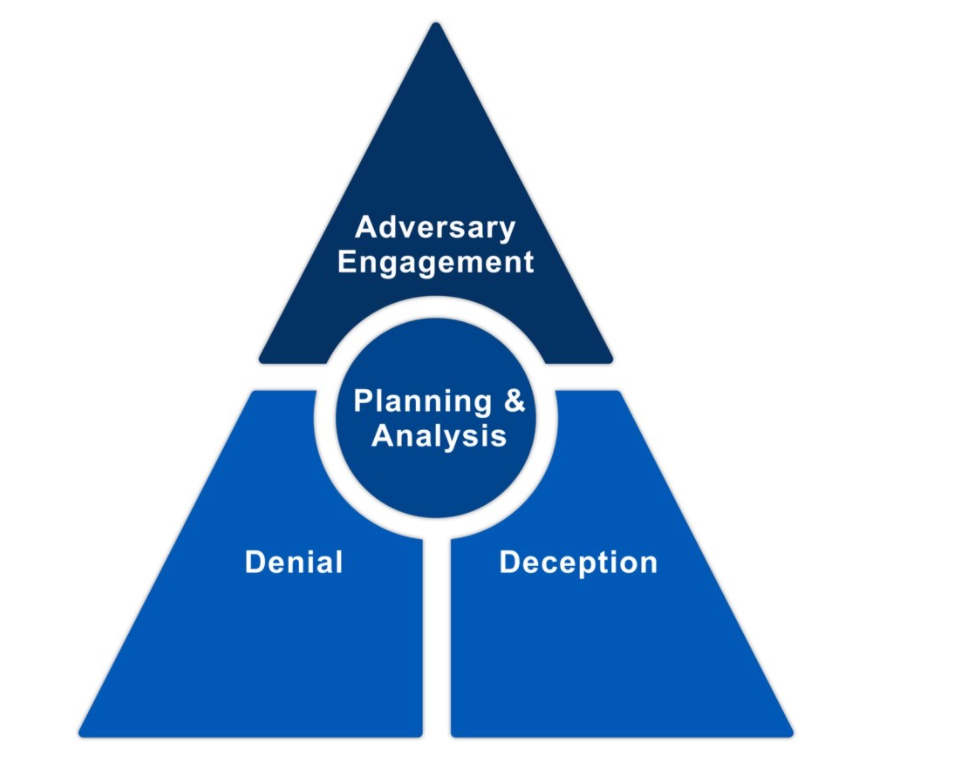
The foundation of adversary engagement, within the context of strategic planning and analysis, is cyber denial and cyber deception [MIT22b]:
While MITRE Engage has not been around for long, the practice of cyber deception has a long history; honeypots for example can be traced back to the 1990s [Spi04, Ch. 3]. MITRE Engage prescribes the 10-Step Process, which was adapted from the process of deception in [RW13, Ch. 19], in Fig. 1: 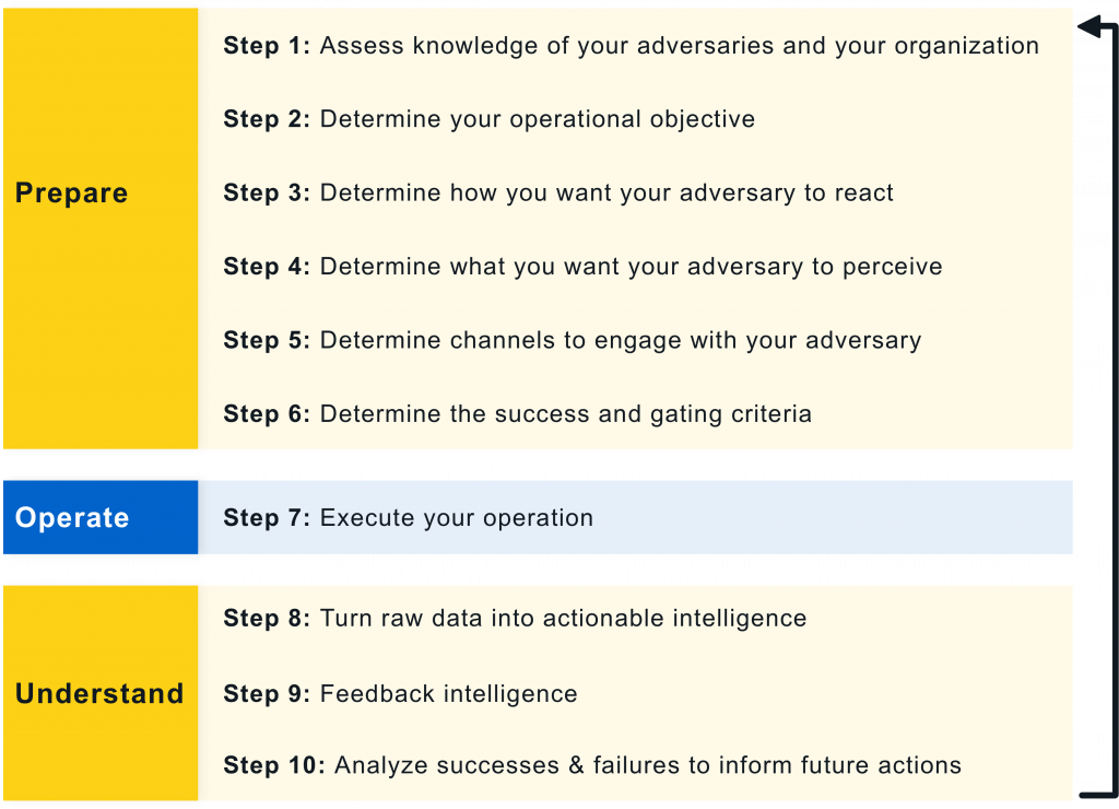 Prepare phase:
Operate phase:
Understand phase:
Example 1: The Tularosa Study
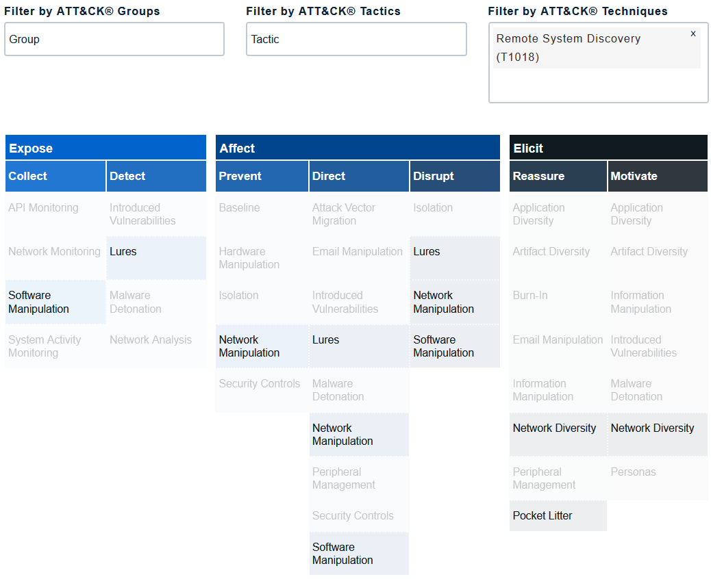
A starting point to practising cyber deception is to combine deception tools (e.g., honeypots and decoy content) with traditional defences (e.g., application programming interface monitoring, backup and recovery) [Heb22]. Contrary to intuition, cyber deception is more effective when adversaries know it is in place, because its presence exerts psychological impact on the adversaries [Heb22]. Supporting evidence is available from the 2018 Tularosa Study [FWSR+18]; watch presentation below: Operationalise the MethodologiesThe foundation of an adversary engagement strategy is the Engage Matrix: The Matrix serves a shared reference that bridges the gap between defenders and decision makers when discussing and planning denial, deception, and adversary engagement activities. The Matrix allows us to apply the theoretical 10-Step Process (see Fig. 1) to an actual operation. The top row identifies the goals: Prepare and Understand, as well as the objectives: Expose, Affect and Elicit.
The second row identifies the approaches, which let us make progress towards our selected goal. The remainder of the Matrix identifies the activities.
References
| ||||||||||||


Model checking | ||||||
|---|---|---|---|---|---|---|
Model checking is a method for formally verifying that a model satisfies a specified property [vJ11, p. 1255]. Model checking algorithms typically entail enumerating the program state space to determine if the desired properties hold. Example 1 [CDW04]
Developed by UC Berkeley, MOdelchecking Programs for Security properties (MOPS) is a static (compile-time) analysis tool, which given a program and a security property (expressed as a finite-state automaton), checks whether the program can violate the security property. The security properties that MOPS checks are temporal safety properties, i.e., properties requiring that programs perform certain security-relevant operations in certain orders. An example of a temporal security property is whether a setuid-root program drops root privileges before executing an untrusted program; see Fig. 1.  References
| ||||||
N |
|---|
NIST Cybersecurity Framework | ||||||||||||||||||||||||||||||
|---|---|---|---|---|---|---|---|---|---|---|---|---|---|---|---|---|---|---|---|---|---|---|---|---|---|---|---|---|---|---|
The National Institute of Standards and Technology (NIST) has an essential role in identifying and developing cybersecurity risk frameworks for voluntary use by owners and operators of critical infrastructure (see Definition 1) [NIS18, Executive Summary]. Definition 1: Critical infrastructure [NIS18, Sec. 1.0]
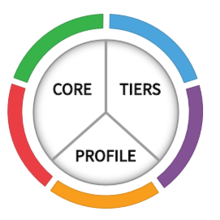
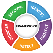
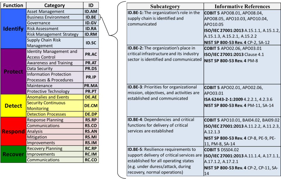
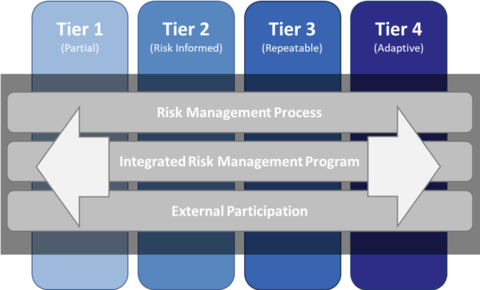
Systems and assets, whether physical or virtual, so vital that the incapacity or destruction of such systems and assets would have a debilitating impact on security, national economic security, national public health or safety, or any combination of those matters. One such framework is the Framework for Improving Critical Infrastructure Cybersecurity (Cybersecurity Framework for short), for which NIST is maintaining an official website. As of writing, the latest version of the NIST Cybersecurity Framework is 1.1 [NIS18]. The Cybersecurity Framework provides a common language for understanding, managing and expressing cybersecurity risks to internal and external stakeholders [NIS18, Sec. 2.0]. The Cybersecurity Framework has three parts: 1️⃣ Framework Core, 2️⃣ Implementation Tiers, and 3️⃣ Framework Profiles.
Watch a more detailed explanation of the Cybersecurity Framework presented at RSA Conference 2018: References
| ||||||||||||||||||||||||||||||