Special | A | B | C | D | E | F | G | H | I | J | K | L | M | N | O | P | Q | R | S | T | U | V | W | X | Y | Z | ALL
M |
|---|
Model checking | ||||||
|---|---|---|---|---|---|---|
Model checking is a method for formally verifying that a model satisfies a specified property [vJ11, p. 1255]. Model checking algorithms typically entail enumerating the program state space to determine if the desired properties hold. Example 1 [CDW04]
Developed by UC Berkeley, MOdelchecking Programs for Security properties (MOPS) is a static (compile-time) analysis tool, which given a program and a security property (expressed as a finite-state automaton), checks whether the program can violate the security property. The security properties that MOPS checks are temporal safety properties, i.e., properties requiring that programs perform certain security-relevant operations in certain orders. An example of a temporal security property is whether a setuid-root program drops root privileges before executing an untrusted program; see Fig. 1.  References
| ||||||
N |
|---|
NIST Cybersecurity Framework | ||||||||||||||||||||||||||||||
|---|---|---|---|---|---|---|---|---|---|---|---|---|---|---|---|---|---|---|---|---|---|---|---|---|---|---|---|---|---|---|
The National Institute of Standards and Technology (NIST) has an essential role in identifying and developing cybersecurity risk frameworks for voluntary use by owners and operators of critical infrastructure (see Definition 1) [NIS18, Executive Summary]. Definition 1: Critical infrastructure [NIS18, Sec. 1.0]
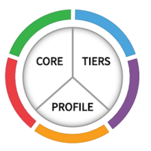
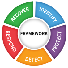
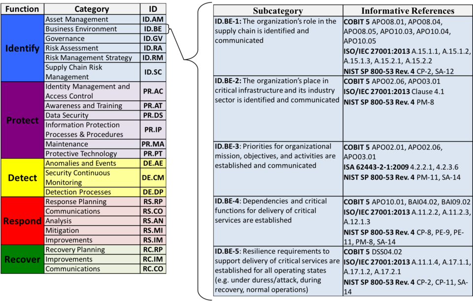
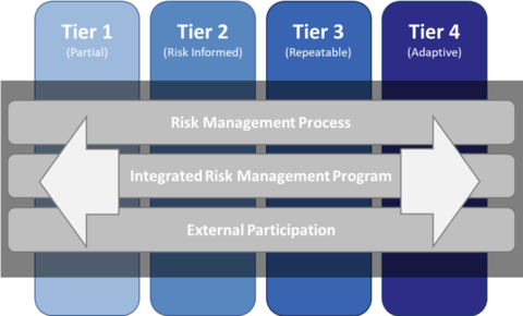
Systems and assets, whether physical or virtual, so vital that the incapacity or destruction of such systems and assets would have a debilitating impact on security, national economic security, national public health or safety, or any combination of those matters. One such framework is the Framework for Improving Critical Infrastructure Cybersecurity (Cybersecurity Framework for short), for which NIST is maintaining an official website. As of writing, the latest version of the NIST Cybersecurity Framework is 1.1 [NIS18]. The Cybersecurity Framework provides a common language for understanding, managing and expressing cybersecurity risks to internal and external stakeholders [NIS18, Sec. 2.0]. The Cybersecurity Framework has three parts: 1️⃣ Framework Core, 2️⃣ Implementation Tiers, and 3️⃣ Framework Profiles.
Watch a more detailed explanation of the Cybersecurity Framework presented at RSA Conference 2018: References
| ||||||||||||||||||||||||||||||

O |
|---|
Open Systems Interconnection (OSI) | ||||||||||||||||||||||||||||
|---|---|---|---|---|---|---|---|---|---|---|---|---|---|---|---|---|---|---|---|---|---|---|---|---|---|---|---|---|
Imagine writing a piece of networking software.
The Open Systems Interconnection (sometimes Open Systems Interconnect or simply OSI) model 1️⃣ enables networking software to be built in a structured manner; 2️⃣ provides an interoperability framework for networking protocols. History: The OSI model was introduced in 1983 by several major computer and telecom companies; and was adopted by ISO as an international standard in 1984 [Imp22].
Watch the following video for a quick overview: Learning the seven layers from Networking Foundations: Networking Basics by Kevin Wallace More details follows. The OSI model is a logical (as opposed to physical) model that consists of seven nonoverlapping layers (going bottom-up, opposite to Fig. 1):
 
The OSI model is not the only networking model. The TCP/IP reference model plays an equally important role in the history of networking. The APRANET and its descendent — the Internet as we know it — are based on the TCP/IP model. The TCP/IP model has only four layers, as shown in Fig. 3. Fig. 3 also shows the different protocols occupying the different layers of the TCP/IP model. Both models use 1️⃣ the transport and lower layers to provide an end-to-end, network-independent transport service; and 2️⃣ the layers above transport for applications leveraging the transport service. Most real-world protocol stacks are developed based on a hybrid of the OSI and TCP/IP models, consisting of these layers (from bottom to top): physical, data link, network, transport, application [TW11, Sec. 1.4.3]. 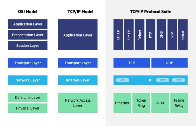 The salient differences between the OSI and TCP/IP models are summarised in Table 1 below.
References
| ||||||||||||||||||||||||||||
P |
|---|
Physical-layer security | ||||
|---|---|---|---|---|
References
| ||||
Physical unclonable function (PUF) | ||||
|---|---|---|---|---|
Physical unclonable functions (PUFs, see Definition 1) serve as a physical and unclonable alternative to digital cryptographic keys. Definition 1: Physical unclonable function (PUF) [GASA20]
A device that exploits inherent randomness introduced during manufacturing to give a physical entity a unique “fingerprint” or trust anchor. Think of a PUF as a keyed hash function, where the key is built-in and unique due to manufacturing variations [GASA20].
Types of PUFs include 1️⃣ optical PUFs, 2️⃣ arbiter PUFs, 3️⃣ memory-based intrinsic PUFs [GASA20].
Watch a high-level introduction to SRAM PUF: References
| ||||
Proximity-1 Space Link Protocol | ||||||||||||
|---|---|---|---|---|---|---|---|---|---|---|---|---|
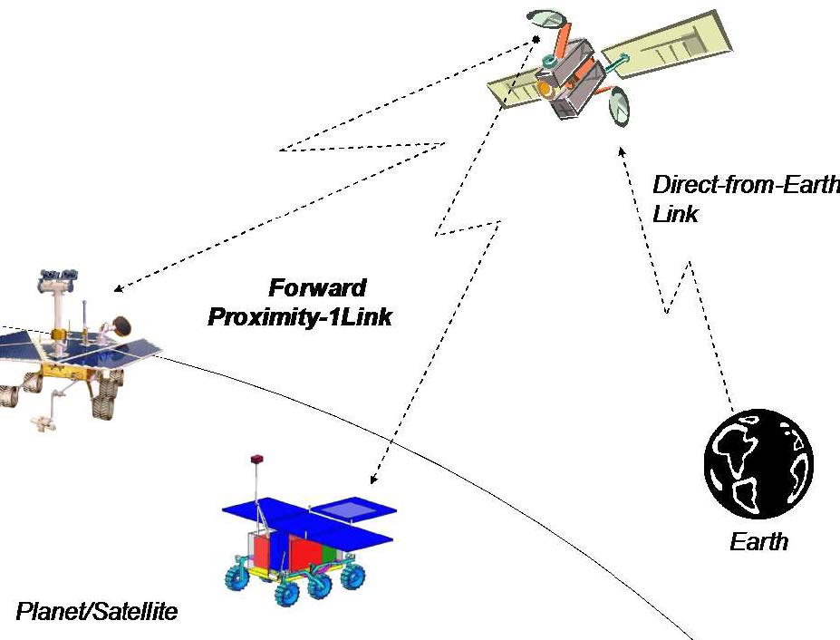
Proximity-1 covers the data link layer [CCS20d] and physical layer [CCS13b]. Proximity-1 enables communications among probes, landers, rovers, orbiting constellations, and orbiting relays in a proximate environment, up to about 100,000 km [CCS13c]. These scenarios are devoid of manual intervention from ground operators, and furthermore, resources such as computational power and storage are typically limited at both ends of the link. In fact, Proximity-1 has been field-tested in the 2004-2005 Mars missions; see Figs. 1-2 for illustration.
In contrast, the AOS/TC/TM Space Data Link Protocols are meant for Earth-deep space links, over extremely long distances. Proximity-1 supports symbol rates of up to 4,096,000 coded symbols per second. Designed for the Mars environment, the physical Layer of Proximity-1 only uses UHF frequencies [CCS13b, Sec. 1.2]. The frequency range consists of 60 MHz between 390 MHz to 450 MHz with a 30 MHz guard-band between forward and return frequency bands, specifically 435-450 MHz for the forward channel and 390-405 MHz for the return channel [CCS13b, Sec. 3.3.2]. References
| ||||||||||||

Public-key cryptography | ||||||||||
|---|---|---|---|---|---|---|---|---|---|---|
Also known as asymmetric-key cryptography, public-key cryptography (PKC) uses a pair of keys called a public key and a private key for 1️⃣ encryption and decryption, as well as 2️⃣ signing and verification. Encryption and decryption For 👩 Alice to send a confidential message to 🧔 Bob,
However,
Signing and verification For 👩 Alice to assure 🧔 Bob a message really originated from her (i.e., for Bob to authenticate her message),
Definition 1: Non-repudiation [NIS13]
A service that is used to provide assurance of the integrity and origin of data in such a way that the integrity and origin can be verified and validated by a third party as having originated from a specific entity in possession of the private key (i.e., the signatory). The ability of PKC to generate and verify signatures gives rise to 📜 digital certificates, an essential feature of PKC. Digital certificates and public-key infrastructure (PKI)Suppose 👩 Alice is somebody everybody trusts.
Definition 3: Digital certificate [ENISA]
Also called a public-key certificate, a digital certificate is an electronic data structure that binds an entity (e.g., an institution, a person, a computer program, a web address) to its public key. Watch a quick introduction to digital certificates on LinkedIn Learning: Digital certificates and signing from Ethical Hacking: Cryptography by Stephanie Domas Digital certificates are only useful if we can trust their signatories. To ensure signatories and hence certificates can be trusted, PKC relies on a public-key infrastructure (PKI, see Definition 3) to work. Definition 3: Public-key infrastructure (PKI)
In ENISA’s certificate-centric definition, a PKI is a combination of policies, procedures and technology needed to manage digital certificates in a PKC scheme. In ITU-T’s [ITU19] key-centric definition, a PKI is an infrastructure able to support the management of public keys able to support authentication, encryption, integrity and non-repudiation services. Watch a quick introduction to PKI from an operational viewpoint on LinkedIn Learning: Cryptography: Public key infrastructure and certificates from CISA Cert Prep: 5 Information Asset Protection for IS Auditors by Human Element LLC and Michael Lester A PKI, as specified in the ITU-T X.509 [ITU19] standard, consist of certification authorities (CAs).
Fig. 1: A two-tier hierarchy of CAs [NCS20, p. 6]. In a 2-tier hierarchy, a root CA issues certificates to intermediate CAs, and intermediate CAs issue certificates to end entities. Intermediate CAs are often organised to issue certificates for certain functions, e.g., a technology use case, VPN, web application. Alternatively, the CAs can be organised by organisational function, e.g., user / machine / service authentication. 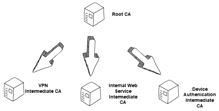 Fig. 2: A three-tier hierarchy of CAs [NCS20, p. 6]. In a 3-tier hierarchy, there is a root CA and two levels of intermediate CAs, in which the lowest layer issues certificates to end entities. This setup is often used to give an extra layer of separation between the root CA and the intermediate issuing certificates to end entities. The number of tiers in a CA hierarchy is a balance between the level of separation required and the tolerable administration overheard.  A PKI also has registration authorities (RAs).
Although the X.509 standard does not specify any validation authority (VA), a VA allows an entity to check that a certificate has not been revoked [NCS20, p. 3].
 Public-key cryptosystemsAlgorithmically speaking, there is more than one way of constructing a public-key cryptosystem. Standard public-key cryptosystems: 1️⃣ Rivest-Shamir-Adleman (RSA) cryptosystem, 2️⃣ elliptic-curve cryptosystems. These cryptosystems rely on the hardness of certain computational problems for their security. The hardness of these computational problems has come under threat of quantum computers and quantum algorithms like Shor’s algorithm. As a countermeasure, NIST has been searching for post-quantum cryptography (PQC, also called quantum-resistant cryptography). As of writing, there are three PQC candidates. References
| ||||||||||

R |
|---|
Rivest-Shamir-Adleman (RSA) cryptosystem | ||
|---|---|---|
See 👇 attachment (coming soon) or the latest source on Overleaf. | ||
Rowhammer | ||||
|---|---|---|---|---|
Not ready for 2023 but see reference below. References
| ||||
S |
|---|
Safe programming languages | ||||||||||||||||||||
|---|---|---|---|---|---|---|---|---|---|---|---|---|---|---|---|---|---|---|---|---|
A safe programming language is one that is memory-safe (see Definition 1), type-safe (see Definition 2) and thread-safe (see Definition 3). Definition 1: Memory safety [WWK+21]
Assurance that adversaries cannot read or write to memory locations other than those intended by the programmer. A significant percentage of software vulnerabilities have been attributed to memory safety issues [NSA22], hence memory safety is of critical importance. Examples of violations of memory safety can be found in the discussion of common weakness CWE-787 and CWE-125. Definition 2: Type safety [Fru07, Sec. 1.1]
Type safety is a formal guarantee that the execution of any program is free of type errors, which are undesirable program behaviours resulting from attempts to perform on some value an operation that is inappropriate to the type of the value. For example, applying a factorial function to any value that is not an integer should result in a type error. Type safety ⇒ memory safety, but the converse is not true [SM07, Sec. 6.5.2], hence type safety is commonly considered to be a central theme in language-based security [Fru07]. Type-safe programming languages, e.g., Java , Ruby, C#, Go, Kotlin, Swift and Rust, have been around for a while. However, memory-unsafe languages are still being used because:
Nevertheless, adoption of type-safe languages, especially Rust, has been on the rise [Cla23]. Thread safety rounds up the desirable properties of type-safe languages. Definition 3: Thread safety [Ora19, Ch. 7]
The avoidance of data races, which occur when data are set to either correct or incorrect values, depending upon the order in which multiple threads access and modify the data. Watch the following LinkedIn Learning video about thread safety: Thread safety from IoT Foundations: Operating Systems Fundamentals by Ryan Hu Rust is an example of a type-safe language that is also thread-safe. References
| ||||||||||||||||||||