Browse the glossary using this index

Special | A | B | C | D | E | F | G | H | I | J | K | L | M | N | O | P | Q | R | S | T | U | V | W | X | Y | Z | ALL

Page: (Previous)   1  2  3  4  5  6  7  8  (Next)
  ALL

S

Picture of Yee Wei Law

Security definitions/notions for encryption

by Yee Wei Law - Tuesday, 22 August 2023, 5:06 PM
 
See 👇 attachment or the latest source on Overleaf.
Tags:

Picture of Yee Wei Law

Side-channel attacks

by Yee Wei Law - Monday, 19 February 2024, 10:36 AM
 

There is a bewildering array of side-channel attacks (see Definition 1).

Definition 1: Side-channel attack [GGF17]

An attack enabled by leakage of information through timing, power consumption, electromagnetic, acoustic and other emissions from a physical system.

It is not an understatement saying that the diversity of side-channel attacks is only limited by the creativity of humankind.

A classic side-channel attack is differential power analysis (🖱 click for in-depth discussion).

Meltdown and Spectre are high-profile side-channel attacks of recent years that exploit the hardware weakness CWE-1037.

Below, we cover two recent attacks that are not as “classic” or “high-profile” but no less interesting.

Example 1

In cybersecurity, the term “air gap” refers to an interface between two systems at which (a) they are not connected physically and (b) any logical connection is not automated (i.e., data is transferred through the interface only manually, under human control) [Shi07].

  • In short, an air gap provides a form of cyber insulation between two systems.

Just like physical insulation can be overcome, so can cyber insulation be.

There is a group of researchers at the Ben-Gurion University of the Negev, including Mordechai Guri in the video below, that specialise in side-channel attacks, especially attacks that overcome air gaps.

Watch Mordechai Guri’s Black Hat 2018 talk about “air-gap jumpers”:

Among the air-gap side-channel attacks investigated so far are PowerHammer [GZBE20], named after the infamous rowhammer attack.

  • PowerHammer enables attackers to exfiltrate information from air-gapped systems by leveraging conducted emission through alternating-current (AC) power lines.
  • Conducted emission is desired or undesired electromagnetic energy that is propagated along a conductor (see European Cooperation for Space Standardization Glossary and Fig. 1).

How PowerHammer works in a nutshell:

  • The attacker infects target computer (transmitting computer in Fig. 2) with malware.
  • The attacker taps the indoor electrical power wiring that is connected to the electrical outlet of the compromised computer, as shown in Fig. 2.
  • The attacker generates conducted emission to exfiltrate data by modulating CPU workload and hence power consumption.

    Simple modulation strategy: encoding 0 with a low frequency and 1 with a high frequency — essentially the technique of binary frequency shift keying (BFSK).

    For low frequency, make a CPU core sleep for a certain number of CPU cycles.

    For high frequency, make a CPU core repeatedly start and stop for a certain number of CPU cycles.

    Fig. 3 illustrates encoding of 0 and 1 with two frequencies.

    The attacker dedicates threads to CPU cores, with one thread for each core, using the POSIX function sched_setaffinity.

    Fig. 4 indicates the more CPU cores involved, the easier it is to separate the two frequencies.

Fig. 1: (a) Conducted emission due to normal computing workload. (b) Conducted emission due to PowerHammer transmissions [GZBE20, Fig. 1].
Fig. 2: Attacker’s malware in transmitting computing encodes data desired by attacker in conducted emission. Attacker’s current probe measures current and indirectly, single-phase power of a three-phase system. Attacker’s measurement computer decodes malware’s transmission [GZBE20, Fig. 6].
  • The attacker analyses and decodes the conducted electromagnetic emission of the compromised computer and thereby exfiltrates the encoded data at the measurement computer in Fig. 2.

Fig. 3: BFSK modulation [GZBE20, Fig. 4].

Fig. 4: Power spectral density of a sample transmission with different number of cores at two different frequencies, namely 10 kHz and 18 kHz [GZBE20, Fig. 11].
Example 2

Quantum key distribution (QKD) is a method for generating and distributing symmetric cryptographic keys with information-theoretic security based on quantum information theory [ETS18].

The earliest QKD protocol is due to Bennett and Brassad [BB84] and is called BB84, named after the authors and the year it was proposed.

BB84 encodes a classic bit in the polarisation state of a photon, which is a discrete variable, hence BB84 is an example of a discrete-variable quantum key distribution (DV-QKD) scheme.

In a typical implementation of BB84, Bob uses single-photon detectors (see sample commercial products from ID Quantique SA) to receive photons from Alice, but this single-photon detector can be an Archilles’ heel of the DV-QKD system, as Durak et al. [DJK22] have shown.

Among the most commonly used single-photon detectors are avalanche photodiodes (APDs), which are photodiodes with internal gain produced by the application of a reverse voltage.

  • APDs have a high level of signal-to-noise ratio (SNR), a short response time, low dark current, and high sensitivity.
  • In APDs, a received photon triggers an avalanche of electrical current, and when the current crosses a certain threshold (milliamps), a digital pulse (tens of nanoseconds, with exponential decay) in the output indicates photon detection; see Fig. 5(a)-(b).
  • An avalanche produces emissions in the form of 1️⃣ a fluorescence flash of light and 2️⃣ radio-frequency (RF) radiation; see Fig. 5(a)-(b).
  • Fig. 5(b)-(c) suggests an APD emits a distinguishable FIR pattern/signature/fingerprint, and thus the RF radiation is an exploitable side channel.
  • BB84 requires 4 APDs for detecting 4 polarisation states: 0° and 90° in the rectilinear basis, 45° and 135° in the diagonal basis; see the D blocks in Fig. 6(a).
  • The APDs are physically separated from each other by tens of centimetres [DJK22, Sec. III], so their RF emissions should be uniquely identifiable.

Fig. 6(b) and Fig. 7 show an experimental setup an attacker can use to gather FIR data, and train a neural network for classifying received RF emission into four polarisation states.

Fig. 5: (a) An APD acts like a downconverter that converts optical-wavelength single photons to RF radiation. (b) A sample frequency response arising from the reflections of APD-originated RF radiation by common structures in a lab. (c) Frequency response resembles that of an finite impulse response (FIR) filter with delays () and reflection coefficients () [DJK22, Fig. 1].
Fig. 6: (a) A typical experimental setup for BB84. (b) Setup used by an attacker to gather FIR data associated with each polarisation state; see also Fig. 7. (c) Setup used by an attacker to infer polarisation state from Bob’s RF side channel [DJK22, Fig. 2].
Fig. 7: Visualised experimental setup, where an ultra-wideband (UWB) antenna (at most 2 m away from the closest APD) is used to capture the RF radiation emitted by the APDs, and a combination of signal processing and machine learning is used to distinguish among 4 polarisation states [DJK22, Fig. 3].

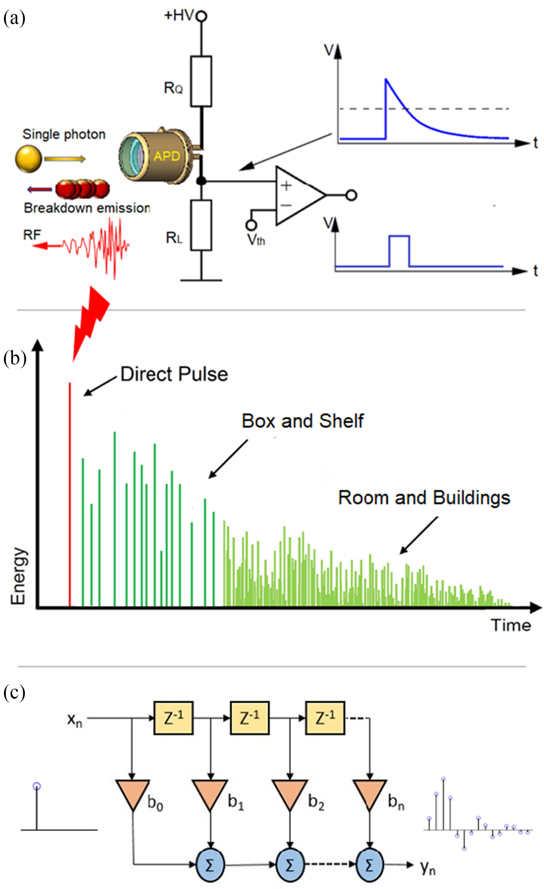
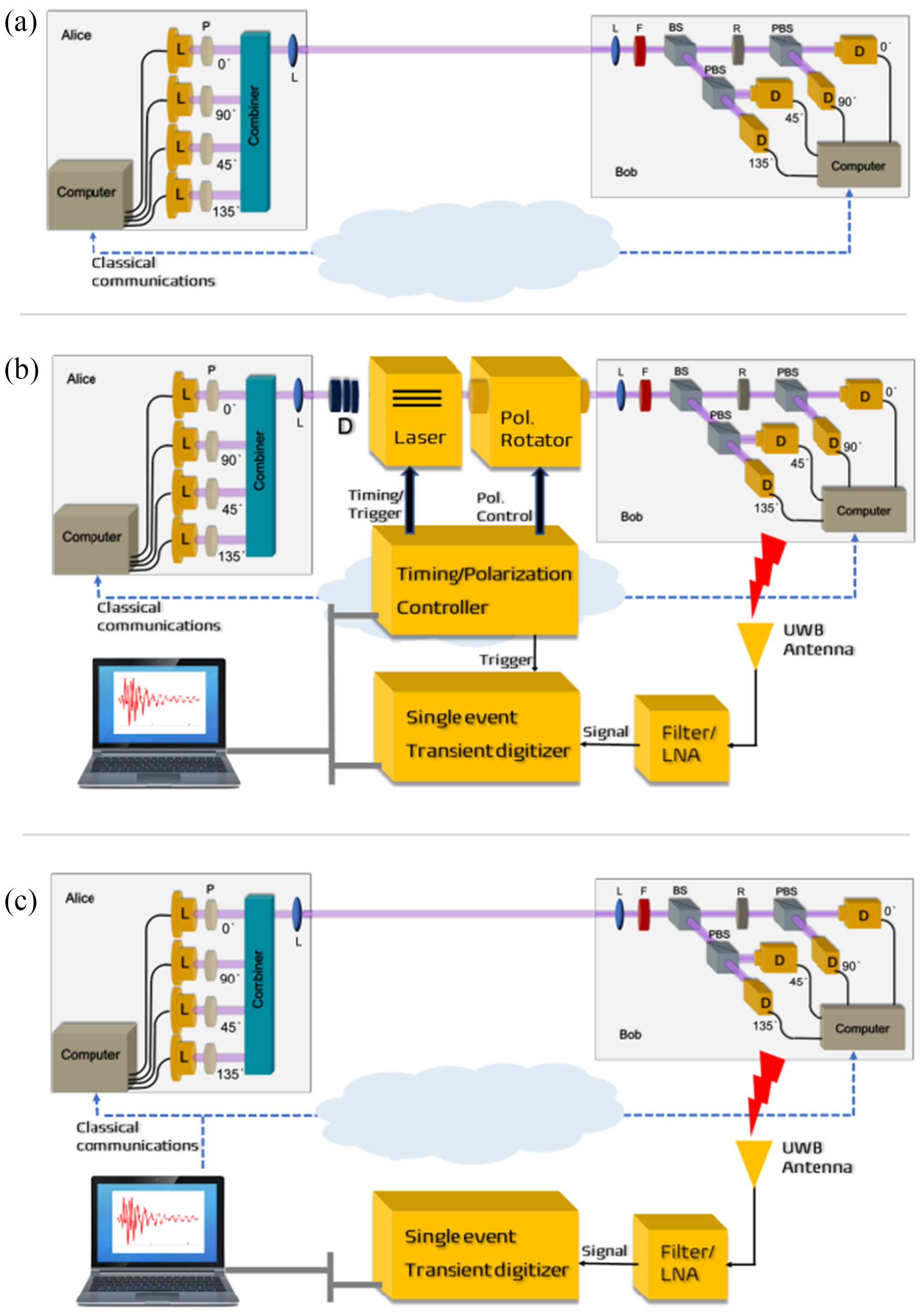
The neural network in Fig. 8 takes a time-domain sample of 256 data points, and can be trained to classify a test sample into one of four polarisation states at high accuracy.

Fig. 8: A 5-layer neural network with 256 input neurons and 2 output neurons (encoding 2 bits of information) [DJK22, Fig. 7].

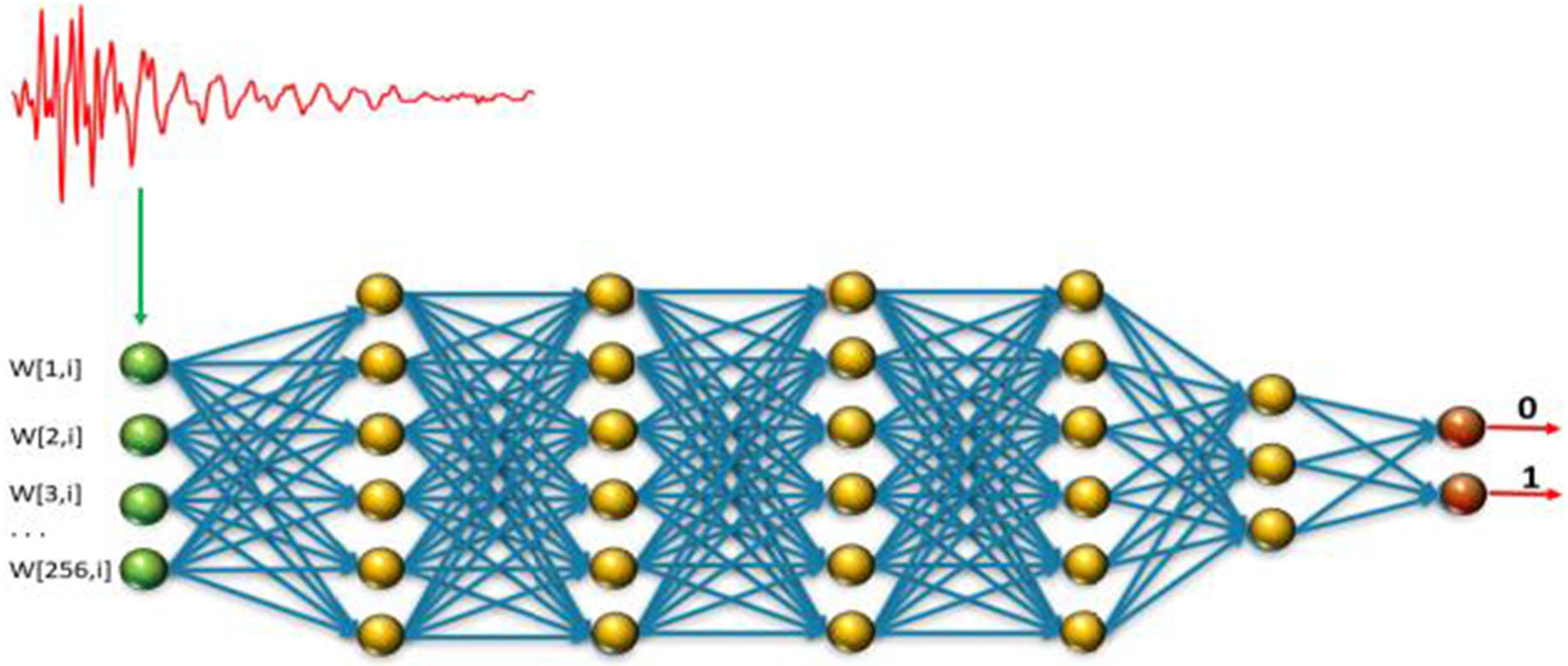
Durak et al.’s [DJK22] results demonstrate feasibility of “cloning” Bob’s qubits using an RF side channel.

Countermeasures

The countermeasures for CWE-1300 apply.

References

[BB84] C. H. Bennett and G. Brassard, Quantum cryptography: Public key distribution and coin tossing, in Proceedings of the International Conference on Computers, Systems & Signal Processing, December 1984, pp. 175–179. Available at https://arxiv.org/abs/2003.06557.
[DJK22] K. Durak, N. C. Jam, and S. Karamzadeh, Attack to quantum cryptosystems through RF fingerprints from photon detectors, IEEE Journal of Selected Topics in Quantum Electronics 28 no. 2: Optical Detectors (2022), 1–7. https://doi.org/10.1109/JSTQE.2021.3089638.
[ETS18] ETSI, Quantum Key Distribution (QKD); Vocabulary, Group Report ETSI GR QKD 007 v1.1.1, December 2018. Available at https://www.etsi.org/deliver/etsi_gr/QKD/001_099/007/01.01.01_60/gr_qkd007v010101p.pdf.
[GGF17] P. A. Grassi, M. E. Garcia, and J. L. Fenton, Digital identity guidelines, NIST Special Publication 800-63-3, June 2017. https://doi.org/10.6028/NIST.SP.800-63-3.
[GZBE20] M. Guri, B. Zadov, D. Bykhovsky, and Y. Elovici, PowerHammer: Exfiltrating data from air-gapped computers through power lines, IEEE Transactions on Information Forensics and Security 15 (2020), 1879–1890. https://doi.org/10.1109/TIFS.2019.2952257.
[Shi07] R. Shirey, Internet Security Glossary, Version 2, IETF RFC 4949, 2007.

Picture of Yee Wei Law

Solar System Internetwork (SSI)

by Yee Wei Law - Thursday, 7 March 2024, 3:16 PM
 

The discussion below provides some historical context, an overview and a description of the network protocol stack of the Solar System Internetwork (SSI).

History

In 1999, the Interagency Operations Advisory Group (IOAG) was established to achieve cross support across the international space community and to expand the enabling levels of space communications and navigation interoperability [CCS14, Foreword].

In 2007, the IOAG chartered a Space Internetworking Strategy Group (SISG) to reach international consensus on a recommended approach for transitioning the participating agencies towards a future network-centric era of space mission operations [CCS14, Foreword].

In 2008, the SISG released a preliminary report on their operations concept for a Solar System Internetwork (SSI) [CCS14, Foreword]; see the 2011 conference version of the report [EDB11].

In 2010, the IOAG finalised the SSI Operations Concept and asked the Consultative Committee for Space Data Systems (CCSDS) to create the SSI architectural definition [CCS14, Foreword].

In 2014, the CCSDS Space Internetworking Services - Delay-Tolerant Networking (SIS-DTN) working group released the official informational report [CCS14].

The SSI architecture is based on international standards and voluntary agreements [CCS14, Executive Summary].

Participation in the SSI is expected to be incremental, and furthermore, the SSI specification and technologies are still evolving.

In fact, the Interplanetary Networking Special Interest Group (IPNSIG), a chapter of the Internet Society, has the vision to develop a secure and robust Solar System Internet, by extending networking to space, from the historical point-to-point, “bent pipe” communication architecture to a store-and-forward, packet-switched design, interconnecting any number of terrestrial and space-borne nodes [KCB+21].

Overview

The fundamental objective of the SSI is to provide automated and internetworked data communication services for space ventures (at least across the solar system) [CCS14, Executive Summary; EDB11, Sec. 2].

The emphasis on automation arises from the need to support communication among the various participants operating in space ventures without requiring a detailed understanding of space communication operations [CCS14, Executive Summary].

Examples of participants include [CCS14, Sec. 2.1]:

  • crewed and robotic space-faring vehicles, often carrying investigative instruments;
  • planetary surface systems, with crew and/or instruments;
  • ground antenna stations;
  • centralised ground-based mission operations centres (MOCs) on Earth;
  • science investigators at widely distributed laboratories on Earth.

The SSI interconnects multiple networks built on two types of networking architectures, namely 1️⃣ the Internet architecture and 2️⃣ the DTN architecture.

Fig. 1 depicts a communication scenario that the SSI architecture is designed to support.

Fig. 1: A sample communication scenario involving two agencies and three missions [CCS14, Figure 2-3].

In Fig. 1,

  • Multiple missions may be involved, and each mission may operate multiple spacecrafts, which may autonomously collaborate on mission objectives.
  • The set of spacecrafts conducting a long-lived mission may change over time, as disabled spacecrafts become decommissioned and new spacecrafts get deployed.
  • Data may be routinely relayed among spacecrafts, even among spacecrafts deployed for different missions, by different space agencies. Furthermore, data may be relayed through different spacecrafts at different times, introducing the possibility of multiple data paths between spacecrafts and MOCs.

To accommodate the multi-agency, multi-mission scenario in Fig. 1, the SSI architecture specifies three stages of functionality:

Protocol stack

The SSI protocol stack is a combination of the Internet Protocol (IP) stack and the Delay-Tolerant Network (DTN) protocol stack, as shown in Fig. 2.

Going top-down along the DTN “facet” (CCSDS term) [CCS14, Sec. C3],

  • DTN applications are applications designed to operate with communications characterised by variable, substantial latencies due to 1️⃣ large signal propagation delays, 2️⃣ lengthy physical communication outages, or 3️⃣ both.

    These applications are implemented to utilise the CCSDS File Delivery Protocol (CFDP) and optionally other DTN application-layer services over a Bundle Protocol (BP) network.

Fig. 2: The composite network protocol stack of the SSI [CCS14, Figure C-9].

Fig. 3: A sample instantiation of the CCSDS protocol stack [CCS20d, Figure 2-1], where CLA = convergence layer adapter.

  • The BP network runs over the Licklider Transmission Protocol (LTP).

    While protocols from the IP suite are limited to scenarios in which network paths are continuously connected and have low latencies, BP network can operate in any scenario in the SSI, including on top of TCP/IP, as Fig. 3 shows.

  • Fig. 3 also shows below the LTP layer, sit the Encapsulation Packet Protocol and Space Packet Protocol.

    The Space Data Link Protocols (SDLPs) sit further down the protocol stack.

  • Among the SDLPs, the Proximity-1 Space Link Protocol is defined for short-range, bi-directional, fixed or mobile radio links, generally used to communicate among probes, landers, rovers, orbiting constellations, and orbiting relays.

    The 1️⃣ Telecommand (TC) SDLP, 2️⃣ Telemetry (TM) SDLP, and 3️⃣ Advanced Orbital Systems (AOS) SDLP [CCS15d] serve other scenarios.

    Fig. 4 demonstrates the usage of AOS-SDLP in a space network and Proximity-1 in a Mars network.

    Fig. 5 demonstrates the usage of Proximity-1 between two space nodes; and the usage of AOS-SDLP and TC-SDLP between a space node and a ground terminal.

    Improving upon the preceding protocols, the Unified Space Data Link Protocol (USLP, not typo) has been designed to meet the requirements of space missions for efficient transfer of space application data of various types and characteristics over space-to-ground, ground-to-space, and space-to-space communications links [CCS21c].

    Fig. 6 maps the protocols discussed so far to the Open System Interconnection (OSI) model.

Fig. 4: An example of how CCSDS protocols are used in a scenario where lander data are transferred using custody transfer to the lander MOC on Earth [ABH21, Figure 9].

Fig. 5: DTN protocol building blocks in an end-to-end ABCBA view [CCS18, Figure 3-3].

In CCSDS terminology [CCS15b, Sec. 1.6.1], an ABCBA view/configuration refers to a multi-hop space communications configuration involving 1️⃣ multiple space and ground elements and 2️⃣ multiple direct earth-space and space-space links. ABCBA configurations nominally include elements from three or more agencies.

Fig. 6: CCSDS protocols and associated security options [CCS19b, Figure 3-1], where SBSP = Streamlined Bundle Security Protocol, SDLS = Space Data Link Security.

References

[ABH21] A. Y. Alhilal, T. Braud, and P. Hui, A roadmap toward a unified space communication architecture, IEEE Access 9 (2021), 99633–99650. https://doi.org/10.1109/ACCESS.2021.3094828.
[CCS14] CCSDS, Solar System Internetwork (SSI) Architecture, Informational Report CCSDS 730.1-G-1, The Consultative Committee for Space Data Systems, July 2014. Available at https://public.ccsds.org/Pubs/730x1g1.pdf.
[CCS15b] CCSDS, Space Communications Cross Support—Architecture Requirements Document, Recommended Practice CCSDS 901.1-M-1, The Consultative Committee for Space Data Systems, May 2015. Available at https://public.ccsds.org/Pubs/901x1m1.pdf.
[CCS15d] CSDS, Space Data Link Protocols—Summary of Concept and Rationale, Informational Report CCSDS 130.2-G-3, The Consultative Committee for Space Data Systems, September 2015. Available at https://public.ccsds.org/Pubs/130x2g3.pdf.
[CCS18] CCSDS, Concepts and Rationale for Streaming Services over Bundle Protocol, Informational Report CCSDS 730.2-G-1, The Consultative Committee for Space Data Systems, September 2018. Available at https://public.ccsds.org/Pubs/730x2g1.pdf.
[CCS19b] CCSDS, The Application of Security to CCSDS Protocols, Informational Report CCSDS 350.0-G-3, The Consultative Committee for Space Data Systems, March 2019. Available at https://public.ccsds.org/Pubs/350x0g3.pdf.
[CCS20d] CCSDS, Space Packet Protocol, Recommended Standard CCSDS 133.0-B-2, The Consultative Committee for Space Data Systems, June 2020. Available at https://public.ccsds.org/Pubs/133x0b2e1.pdf.
[CCS21c] CCSDS, Unified Space Data Link Protocol, Recommended Standard CCSDS 732.1-B-2, The Consultative Committee for Space Data Systems, October 2021. Available at https://public.ccsds.org/Pubs/732x1b2.pdf.
[EDB11] C. D. Edwards, M. Denis, and L. Braatz, Operations concept for a Solar System Internetwork, in 2011 Aerospace Conference, 2011, pp. 1–9. https://doi.org/10.1109/AERO.2011.5747340.
[KCB+21] Y. Kaneko, V. Cerf, S. Burleigh, M. Luque, and K. Suzuki, Strategy toward Solar System Internet for humanity, Report from Strategy Working Group, Interplantery Networking Special Interest Group, Internet Society, June 2021. Available at https://ipnsig.org/wp-content/uploads/2021/10/IPNSIG-SWG-REPORT-2021-3.pdf.
[WZP18] P. Wan, Y. Zhan, and X. Pan, Solar system interplanetary communication networks: architectures, technologies and developments, Science China Information Sciences 61 no. 4 (2018), 040302. https://doi.org/10.1007/s11432-017-9346-1.

Picture of Yee Wei Law

Solar System Internetwork (SSI) Stage 1 Mission Functionality

by Yee Wei Law - Tuesday, 16 May 2023, 11:55 AM
 

This continues from Solar System Internetwork (SSI).

The Stage 1 Mission Functionality of the Solar System Internetwork (SSI) is the automation of basic communication processes between vehicles and Mission Operations Centers (MOCs) that might be performed for a single space flight mission, including [CCS14, Sec. 3]:

  • the initiation and termination of transmissions;
  • the scheduling of data for transmission according to priority designations declared by SSI users;
  • the segmentation and reassembly of large data items for transmission in small increments;
  • the retransmission of data that were lost or corrupted in transmission;
  • the relaying of data from one entity to another via some other entity pre-selected by management.

Fig. 1 depicts a sample communication scenario between two SSI nodes: one onboard the spacecraft and another at the spacecraft MOC.

  • The SSI data flow between these two nodes is established by requesting a space link session from the Earth station control center.
  • Data are exchanged via the Earth station by link-layer mechanisms, which are nominally based on the CCSDS Space Link Extension (SLE) service [CCS13].
Fig. 1: Sample communication scenario in a simple network topology [CCS14, Figure 3-1].

The network configuration in Fig. 1 can be extended by setting up a separate SSI node for use by the instrument MOC, enabling the instrument MOC to operate on native instrument data flows securely routed through the node at the spacecraft MOC.

Prerequisites and protocols

To be part of the SSI, each node must be configured to run the Bundle Protocol (BP), i.e., a Bundle Protocol Agent (BPA) must be deployed at each node.

For each node on the Earth surface, a Convergence-Layer Adapter (CLA) must be deployed underneath BP, enabling the node to communicate with other Earth-bound nodes via the Internet.

For interoperation with the Internet, the CLA can use the Transmission Control Protocol (TCP) and User Datagram Protocol (UDP), or potentially the Licklider Transmission Protocol (LTP) running on top of UDP/Internet Protocol (IP).

References

[CCS13] CCSDS, Space Communications Cross Support—Architecture Description Document, Informational Report CCSDS 901.0-G-1, The Consultative Committee for Space Data Systems, November 2013.
[CCS14] CSDS, Solar System Internetwork (SSI) Architecture, Informational Report CCSDS 730.1-G-1, The Consultative Committee for Space Data Systems, July 2014.

Picture of Yee Wei Law

Space Attack Research and Tactic Analysis (SPARTA)

by Yee Wei Law - Wednesday, 1 March 2023, 5:19 PM
 

The Aerospace Corporation created the Space Attack Research and Tactic Analysis (SPARTA) cybersecurity matrix

  • to address the information and communication barriers that hinder the identification and sharing of space-cyber Tactic, Techniques, and Procedures (TTP);
  • to provide unclassified information to space professionals about cyber threats to spacecraft.

The SPARTA matrix is a specialisation of the MITRE ATT&CK matrix for defining and categorising commonly identified activities that contribute to spacecraft compromises.

The nine SPARTA tactics shown in the top row of Fig. 1 are a subset of the tactics in MITRE ATT&CK.

Fig. 1: The main attack tactics and techniques in SPARTA. Every technique accompanied by a double vertical sign, ⏸, expands into sub-techniques not shown here.

Under each SPARTA tactic in Fig. 1, each of the main techniques accompanied by a double vertical sign, namely ⏸, can be divided into sub-techniques. For example, under tactic “Reconnaissance” (ST0001), the technique “Gather Spacecraft Design Information” (REC-0001) can be divided into 1️⃣ Software (REC-0001.01), 2️⃣ Firmware (REC-0001.02), 3️⃣ Cryptographic Algorithms (REC-0001.03), 4️⃣ Data Bus (REC-0001.04), 5️⃣ Thermal Control System (REC-0001.05), 6️⃣ Manoeuvre and Control (REC-0001.06), 7️⃣ Payload (REC-0001.07), 8️⃣ Power (REC-0001.08), and 9️⃣ Fault Management (REC-0001.09).

Example 1: Payload

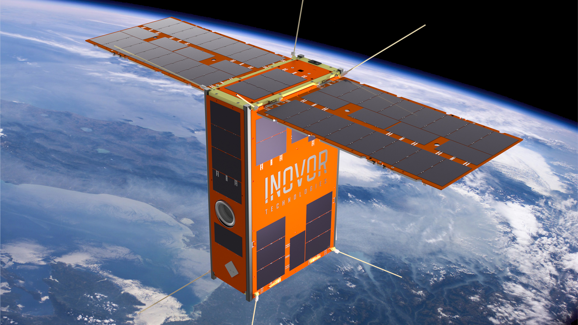
The South Australian 6U CubeSat Kanyini has two payloads: 1️⃣ a hyperspectral imager called HyperScout 2 for earth observation, and 2️⃣ an Internet-of-Things communications module.

Example 2: Applying SPARTA to modelling a recent cyber attack

Watch a quick overview of the attack called PCspooF:

A mixed-criticality system (MCS) is an embedded computing platform in which application functions of different criticalities share computation and/or communication resources [EDN16].

A mixed time-criticality system is an MCS where the criticality is messaging timeliness.

Time-Triggered Ethernet (TTEthernet), as standardised in SAE AS6802, defines algorithms for clock synchronisation, clique detection, startup, and restart for switches and end systems to achieve fault-tolerant synchronisation in an Ethernet-based (IEEE 802.3) mixed time-criticality system.

TTEthernet is used in avionics, industrial control systems (including those for power systems) and automotive systems [LPDK23], so any security vulnerability in TTEthernet would have wide-reaching consequences.

  • In avionics, TTEthernet is used as a bus service for a variety of spacecraft including NASA’s Orion capsule, NASA’s Lunar Gateway space station, and ESA’s Ariane 6 launcher [The22].

How TTEthernet works [LPDK23]

A TTEthernet network contains two types of devices: switches and end systems.

Fault-tolerance is enabled by network redundancy, and each redundant network is called a plane; Fig. 2 shows an example of a system using two planes.

Time-triggered (TT) design = All TTEthernet devices are tightly synchronised and the behaviour of the network is determined by a global schedule made offline and loaded onto each TTEthernet device before deployment.

Fig. 2: TTEthernet provides redundancy to ESA’s Ariane 6 launcher [Fid15, slide 19].
Fig. 3: In TTEthernet, TT traffic is synchronous with sub-microsecond jitters, whereas BE traffic and rate-constrained traffic are asynchronous  [Fid15, slide 16].

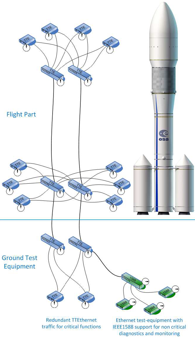
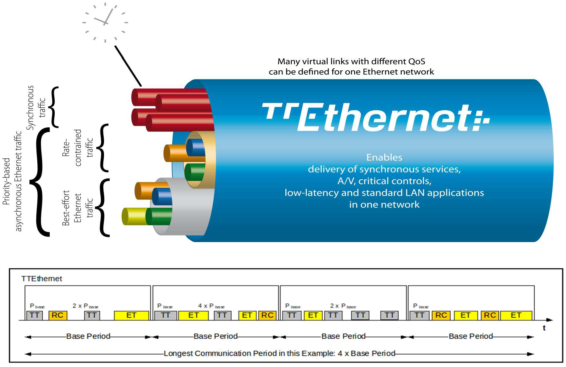
The global schedule specifies when TT frames are forwarded and expected to arrive.

The latency and jitter of TT traffic can be reduced to below 13 μs and 1 μs respectively [Fid15, slide 12].

TTEthernet also carries best-effort (BE, i.e., regular) Ethernet traffic and rate-constrained Avionics Full Duplex Switched Ethernet (AFDX, as standardised in ARINC Specification 664 P7-1) traffic; see Fig. 3.

TTEthernet switches forward BE traffic around the pre-scheduled TT traffic when bandwidth permits.

Mechanisms exist to isolate TT traffic from BE traffic, e.g.,

  • there are windows reserved for TT traffic only;
  • TT and BE frames are stored in different switch buffers.

Central to TTEthernet is a synchronisation protocol, in which a device can participate as 1️⃣ a sync master, 2️⃣ a compression master, or 3️⃣ a sync client.

  • Typically, a subset of the end systems serve as sync masters, while 1-2 switches per plane serve as compression masters.
  • The remaining devices serve as sync clients.

Devices exchange protocol control frames (PCFs) every integration cycle.

  • At the beginning of each integration cycle, every sync master sends a PCF containing its local clock value to the compression masters.
  • The compression masters average the received clock values, then send out the average in a new PCF to the sync masters and clients, which then correct their local clocks.

Receiving certain PCFs from a compression master can cause sync masters and clients to lose synchronisation.

  • An example of such PCFs is “coldstart acknowledgement”, which tells a sync master another sync master detected loss of synchronisation and is reestablishing it.
  • Since a PCF can cause de-synchronisation, TTEthernet requires each compression master to be a self-checking pair, which only produces a PCF if two independent processors agree on the contents.

Attacker/threat model for PCspooF

The PCspooF attack is feasible provided:

  • Attacker has access to at least one BE device, e.g.,
    • by supplying such a device (as a malicious supplier) for integration into the TTEthernet network before the network is deployed;
    • by connecting the device to the TTEthernet network after the network has been deployed.
  • Attacker can control the BE device operating in one plane; see Fig. 4.
  • Attacker-controlled BE device includes additional circuit components for conducting electromagnetic interference (EMI) through its Ethernet cable into a switch; see Fig. 5.
Fig. 4: Attacker controls one BE device in one plane [LPDK23, Fig. 1].
Fig. 5: Rogue BE device injects PCFs via EMI [LPDK23, Fig. 3].

The PCspooF attack

PCspooF is a cyber-physical attack that attempts to disrupt the TTEthernet synchronisation protocol by spoofing PCFs, and thereby inflict denial of service on its victim.

The attack happens in two stages:

  • Stage 1️⃣: This is the cyber stage, where the attacker fabricates a valid PCF.

    Fig. 6: (Top) Standard Ethernet frame vs (Bottom) TTEthernet frame [Lov15, Fig. 3].

    A PCF has the same structure as a standard minimum-sized Ethernet frame, but instead of a destination MAC address, it has a 4-byte Critical Traffic Marker (a special value used to identify all PCFs and TT traffic) and a 2-byte Virtual Link ID (also called Critical Traffic ID [Lov15], which identifies the source of a PCF); see Fig. 6.

    These two fields 👆 must match the values specified in the network schedule loaded onto the TTEthernet devices. These two fields happen to be the only fields that pose a challenge to spoof.

    Skipping the details [LPDK23, Sec. IIIA], an attacker can determine valid Critical Traffic Markers by abusing the Address Resolution Protocol and trying a maximum of around one billion possible values.

    Skipping the details again [LPDK23, Sec. IIIA], an attacker can try to use 4071 or 4070 as the Virtual Link ID, or in the worst case, try a maximum of 65536 values.

    The fabricated PCF is stored inside the payload of a benign BE frame, because TTEthernet switches drop PCFs from BE devices.

    The next stage is to trick a switch into forwarding the aforementioned BE frame as a PCF.

  • Stage 2️⃣: This is the physical stage, where the attacker uses EMI to convert a BE frame into a PCF during transmission.

    This is an example of a link reset attack, which in turn is an example of a packet-in-packet attack [GBM+11].

    Scenario: a BE device is transmitting to a switch, but the PHY preamble becomes corrupted, and consequently the PHY layer of the switch resets itself.

    Attacker uses the opportunity to send packet below:

    Fig. 7: Link reset attack, a type of packet-in-packet attack, uses a long preamble and embeds a malicious packet in a trojan packet [LPDK23, Fig. 5].

    In Fig. 7, the PHY layer and outgoing port of the switch recover during the transmission of the fake preamble.

    Result: Inner frame, which contains the fake PCF, gets sent.

    Corruption of PHY preamble can be achieved through EMI; see Figs. 8-9.

    Fig. 8: Common-mode voltage surge on an Ethernet twisted pair can cause EMI in spite of inductive/magnetic isolation [LPDK23, Fig. 6].
    Fig. 9: Implementing common-mode voltage surge and thereby EMI using an NPN BJT and a spark gap [LPDK23, Fig. 7].

Applying SPARTA

Using the language of SPARTA, these attack stages can be identified [The22]: 1️⃣ Reconnaissance, 2️⃣ Resource Development, 3️⃣ Initial Access, 4️⃣ Execution, 5️⃣ Lateral Movement, 6️⃣ Impact

Table 1 and Table 2 map these attack stages to the attack steps in PCspooF.

Table 1: The first three stages of PCspooF.
Reconnaissance (ST0001) Resource Development (ST0002) Initial Access (ST0003)
  • Gather Spacecraft Design Information (REC-0001), and specifically, Data Bus (REC-0001.04):

    😈 Attacker gathers information required for successful spoofing of TTEthernet frame fields (e.g., Critical Traffic Marker, Virtual Link ID) and design of EMI-injecting PCB.

  • Gather Supply Chain Information (REC-0008), and specifically, Hardware (REC-0008.01):

    😈 Attacker gathers information on the hardware in use, e.g., TTEthernet utilisation, EMI target.

  • Eavesdropping (REC-0005):

    😈 Attacker eavesdrops on the network to infer valid Critical Traffic Markers and Virtual Link IDs from devices’ responses or lack of response.

  • Stage Capabilities (RD-0004), and specifically, Identify/Select Delivery Mechanism (RD-0004.01):

    😈 Attacker identifies the ideal BE device to use for executing the attack.

  • Compromise Supply Chain (IA-0001), and specifically, Hardware Supply Chain (IA-0001.03):

    😈 Attacker sneaks the attacking BE device into the supply chain before or after the deployment of the targeted TTEthernet network.

  • Auxiliary Device Compromise (IA-0011):

    😈 Attacker investigates potential use of a USB/generic hardware vector instead of a BE device.

Table 2: The last three stages of PCspooF.
Execution (ST0004) Lateral Movement (ST0007) Impact (ST0009)
  • Time Synchronised Execution (EX-0008):

    😈 Attacker implements a “ticking timebomb” trigger, which activates attack after a preset amount of post-deployment time.

  • Flooding (EX-0013), and specifically, Erroneous Input (EX-0013.02):

    😈 Attacker brute-forces ARP requests and emissions of EMI.

  • Exploit Hardware/Firmware Corruption (EX-0005), and specifically, Design Flaws (EX-0005.01):

    😈 Attacker exploits weaknesses permitting aggressive ARP polling of BE devices, gathering of information (e.g., Critical Traffic Markers, Virtual Link IDs), and link reset attacks for spoofing PCFs (see Fig. 7).

  • Spoofing (EX-0014), and specifically, Bus Traffic (EX-0014.02):

    😈 Attacker injects spoofed PCFs via EMI-based link reset attacks.

  • Exploit Lack of Bus Segregation (LM-0002):

    😈 Attacker is enabled by the situation where critical (TT) and non-critical (BE) components share the same physical networking infrastructure to use a non-critical component (BE device) to disrupt the operations of critical components (TT devices).

  • Disruption (IMP-0002):

    😈 TTEthernet synchronisation broken, critical operations not being performed, leading to disruption of critical spacecraft operations (e.g., manoeuvring, sensing, communications) and overall mission.

References

[EDN16] R. Ernst and M. Di Natale, Mixed criticality systems—a history of misconceptions?, IEEE Design & Test 33 no. 5 (2016), 65–74. https://doi.org/10.1109/MDAT.2016.2594790.
[Fid15] C. Fidi, Time-Triggered Ethernet: CCSDS Meeting, slides, March 2015. Available at https://cwe.ccsds.org/sois/docs/SOIS-APP/Meeting%20Materials/2015/Spring/SOIS%20Plenary/2015-03-23_TTEthernet-Overview_V1.0.pdf.
[GBM+11] T. Goodspeed, S. Bratus, R. Melgares, R. Shapiro, and R. Speers, Packets in Packets: Orson Welles’ In-Band Signaling Attacks for Modern Radios, in WOOT’11: 5th USENIX Workshop on Offensive Technologies, 2011. Available at https://www.usenix.org/legacy/event/woot11/tech/final_files/Goodspeed.pdf.
[Lov15] A. Loveless, On TTEthernet for Integrated Fault-Tolerant Spacecraft Networks, in AIAA SPACE 2015 Conference and Exposition, 2015. https://doi.org/10.2514/6.2015-4526.
[LPDK23] A. Loveless, L. Phan, R. Dreslinski, and B. Kasikci, PCspooF: Compromising the Safety of Time-Triggered Ethernet, in 2023 IEEE Symposium on Security and Privacy, IEEE Computer Society, Los Alamitos, CA, USA, May 2023, pp. 572–587. https://doi.org/10.1109/SP46215.2023.00033.
[The22] The Aerospace Corporation, Introducing SPARTA using PCSpooF: Cyber Security for Space Missions, Medium, December 2022. Available at https://aerospacecorp.medium.com/sparta-cyber-security-for-space-missions-4876f789e41c.

Picture of Yee Wei Law

Space Packet Protocol (SPP)

by Yee Wei Law - Saturday, 27 May 2023, 3:51 PM
 

Introduction

In many space applications, it is desirable to have a single, common application-layer data structure for the creation, storage, and transport of variable-length application-layer data.

These data is expected to be 1️⃣ exchanged and stored on board, 2️⃣ transferred over one or more space data links, and 3️⃣ used within ground systems.

It is often necessary to identify the 1️⃣ type, 2️⃣ source, and/or 3️⃣ destination of these data.

The preceding needs motivate the definition of the Space Packet Protocol (SPP).

The SPP is designed as a self-delimited carrier of a data unit — called a Space Packet — that contains an application process identifier (APID) used to identify the data contents, data source, and/or data user within a given enterprise [CCS20d, Sec. 2.1.1].

Fig. 1 shows where the SPP sits in the CCSDS protocol stack.

Fig. 2 shows a communication scenario between a spacecraft and a ground terminal, where the SPP plays an important role.

Fig. 1: The SPP sits above the data link layer and below the upper layers in the CCSDS protocol stack [CCS20d, Figure 2-1], where CLA = convergence layer adapter.

Fig. 2: A sample communication scenario [CCS20a, Figure 9-12], featuring mission operations (MO) applications residing in the spacecraft’s onboard computer (OBC).

All OBC apps are under the control of a real-time operating system (RTOS); with the striped blocks running in hard real time.

Science operations (SO) functions are executed through Message Transfer Service, File and Packet Store Services, etc.

The yellow blocks represent the spacecraft onboard interface services (SOIS), and the SPP is one of these services.

Between the SPP and the MO applications sits the Message Abstraction Layer (MAL) [CCS13a], an important component of CCSDS’s Missions Operations Framework.

For applications on separate onboard computers, communications pass through the whole stack and use the physical subnetwork to communicate.

For applications on the same computer, communications pass through the stack to a local loopback function in the software bus.

APID

APIDs are unique in a single naming domain [CCS20d, Sec. 2.1.3]

An APID naming domain usually corresponds to a spacecraft, or an element of a constellation of space vehicles.

Every space project allocates the APIDs to be used in a naming domain.

More precisely, the space project assigns APIDs to managed data paths within a naming domain.

Open-source implementations

The following open-source implementations are known at the time of writing:

References

[CCS13a] CCSDS, Mission Operations Message Abstraction Layer, Recommended Standard CCSDS, The Consultative Committee for Space Data Systems, March 2013. Available at https://public.ccsds.org/Pubs/521x0b2e1.pdf.
[CCS20a] CCSDS, Application and Support Layer Architecture, Informational Report CCSDS 371.0-G-1, The Consultative Committee for Space Data Systems, November 2020. Available at https://public.ccsds.org/Pubs/371x0g1.pdf.
[CCS20d] CCSDS, Space Packet Protocol, Recommended Standard CCSDS 133.0-B-2, The Consultative Committee for Space Data Systems, June 2020. Available at https://public.ccsds.org/Pubs/133x0b2e1.pdf.

Picture of Yee Wei Law

Spectre attacks

by Yee Wei Law - Monday, 3 April 2023, 11:34 AM
 

The Spectre attacks exploit the weakness CWE-1037 “Processor Optimization Removal or Modification of Security-critical Code”.

Modern processors use branch prediction and speculative execution to maximise performance, but the implementations of these optimisations in many processors were found to have broken a range of software security mechanisms, including operating system process separation, containerisation, just-in-time (JIT) compilation, and countermeasures to cache timing and side-channel attacks [KHF+20].

Watch the presentation given by one of the discoverers of Spectre attacks at the 40th IEEE Symposim on Security and Privacy:

More information on the Meltdown and Spectre website.

References

[KHF+20] P. Kocher, J. Horn, A. Fogh, D. Genkin, D. Gruss, W. Haas, M. Hamburg, M. Lipp, S. Mangard, T. Prescher, M. Schwarz, and Y. Yarom, Spectre attacks: Exploiting speculative execution, Commun. ACM 63 no. 7 (2020), 93 – 101. https://doi.org/10.1145/3399742.

Picture of Yee Wei Law

Spread spectrum and frequency hopping

by Yee Wei Law - Wednesday, 24 May 2023, 11:26 AM
 

Frequency hopping is one of two main spread spectrum techniques.

Spread spectrum

A spread-spectrum signal is a low-probability-of-intercept (LPI) signal with extra modulation that expands the signal bandwidth greatly beyond what is required by the underlying channel code (e.g., low-density parity-check codes) and modulation [Tor18].

High-level idea [Ada01, pp. 123-124]:

  • Sender modulates its signal such that signal energy is spread in frequency, and the resultant frequency spectrum is orders of magnitude wider than the information bandwidth (i.e., what is required to carry the signal’s information).
  • A synchronisation scheme exists between the sender and the intended receiver that enables the intended receiver to remove the spreading modulation and process the received signal in the information bandwidth; see Fig. 1.
  • Unintended receivers without knowledge of the synchronisation scheme cannot narrow the signal bandwidth and recover the original signal due to the low signal-to-noise ratio.
Fig. 1: Spread-spectrum signals are broadcast with much wider bandwidth than the information bandwidth [Ada01, Figure 7-1]. The intended receiver can reduce the bandwidth to the information bandwidth, whereas the unintended receivers cannot.

Spread-spectrum communication systems are useful for 1️⃣ suppressing interference, 2️⃣ making secure communications difficult to detect and process, 3️⃣ accommodating fading and multipath channels, and 4️⃣ providing multiple-access capability.

Spread-spectrum signals cause relatively minor interference to other systems operating in the same spectral band.

Two dominant spread-spectrum systems: 1️⃣ direct-sequence and 2️⃣ frequency-hopping.

Frequency-hopping spread spectrum (FHSS)

Intuition: If using one communication channel allows our adversary to sense our channel and subsequently jam it, then it would make sense for us to hop 🐇 from one channel to channel in such a way that it is hard to detect.

The sequence of carrier frequencies is called the frequency-hopping pattern; see Fig. 2.

The set of possible carrier frequencies is called the hopset.

Each of the frequency channel is defined as a spectral region that 1️⃣ includes a single carrier frequency of the hopset as its centre frequency and 2️⃣ has a bandwidth large enough to include most of the power in a single pulse.

The rate at which the carrier frequency changes is the hop rate.

The time interval between hops is the hop interval, and its length is called hop duration ( in Fig. 2).

Fig. 2: A sample frequency-hopping pattern with hop duration and hopping bandwidth [Tor18, Fig. 3.1].

The frequency band within which hopping occurs is the hopping band, and its bandwidth is called hopping bandwidth ( in Fig. 2).

Figs. 3-4 show the general form of a frequency-hopping transmitter and the general form of a frequency-hopping (FH) receiver respectively.

Fig. 3: The general form of an FH transmitter [Tor18, Fig. 3.2a].

Fig. 4: The general form of an FH receiver [Tor18, Fig. 3.2b].

On the transmitter end in Fig. 3, the pattern generator generates a set of pattern-control bits at the hop rate.

The frequency synthesiser synthesises an FH pattern based on the pattern-control bits.

To ensure that an FH pattern is difficult to reproduce or dehop by an adversary, the pattern should be 1️⃣ pseudorandom with a large period and 2️⃣ as uniformly distributed over the frequency channels as possible.

The data-modulated signal is mixed with the FH pattern to produce the FH signal.

On the receiver end in Fig. 4, the same FH pattern on the transmitter end is replicated here in synchrony.

The mixing operation, called dehopping, removes the FH pattern from the received signal.

The bandpass filter removes the double-frequency components and produces the data-modulated dehopped signal.

Example 1

An example of commercial transceivers that support FHSS is Murata’s DNT24 series of 2.4 GHz FHSS wireless transceivers [Wil14].

These transceivers support the establishment of a store-and-forward (i.e., delay-tolerant) network (see Fig. 5), which consists of a base node connected to router nodes, which are in turn connected to remote nodes.

Fig. 5: An example of a store-and-forward network formed by DNT24 transceivers [Wil14, Figure 2.3.1].

For base nodes, the hop duration can range from 8 ms to 100 ms, and has the default value of 20 ms [Wil14, Sec. 7.4].

Other nodes synchronise their hop duration with the base.

Pros

Compared to direct-sequence spread spectrum (DSSS), FHSS 1️⃣ offers more resilience to interference, and is thus better suited for co-located systems; 2️⃣ enables higher channel utilisation [Wil14].

DSSS also requires more circuitry (higher cost) to implement, is more energy-consuming and more sensitive to environmental effects [Law05, Sec. 2.3.2].

Cons

However, FHSS systems require an initial acquisition period during which the receiver must lock on to the moving carrier of the transmitter before any data can be sent, which typically takes several seconds [Wil14].

References

[Ada01] D. Adamy, EW 101 - A First Course in Electronic Warfare, Artech House, 2001. Available at https://app.knovel.com/hotlink/toc/id:kpEWAFCEW7/ew-101-first-course-in/ew-101-first-course-in.
[Law05] Y. W. Law, Key management and link-layer security of wireless sensor networks: energy-efficient attack and defense, Ph.D. thesis, University of Twente, 2005. https://doi.org/10.3990/1.9789036522823.
[Tor18] D. Torrieri, Principles of Spread-Spectrum Communication Systems, fourth ed., Springer Cham, 2018. https://doi.org/10.1007/978-3-319-70569-9.
[Wil14] R. Willett, DNT24 Series, 2.4 GHz Spread Spectrum Wireless Transceivers, Integration Guide, 2014. Available at https://www.murata.com/-/media/webrenewal/products/connectivitymodule/asset/pub/rfm/data/dnt24_integration.ashx.

Picture of Yee Wei Law

Stream ciphers

by Yee Wei Law - Monday, 4 September 2023, 11:11 PM
 
See 👇 attachment or the latest source on Overleaf.
Tags:

Picture of Yee Wei Law

Systems Security Engineering

by Yee Wei Law - Tuesday, 7 March 2023, 3:21 PM
 

NIST provides guidelines on engineering trustworthy (see Definition 1) and cyber-resilient (see Definition 2) systems through NIST SP 800-160 volumes 1 and 2 [RWM22, RPG+21], to be used in conjunction with

  • ISO/IEC/IEEEE International Standard 15288:2015 [ISO15],
  • NIST SP 800-37 [Joi18] and
  • NIST SP 800-53 [Joi20].
Definition 1: Trustworthy [RWM22, p. 1]

Worthy of being trusted to fulfill whatever critical requirements may be needed for a particular component, subsystem, system, network, application, mission, enterprise or other entity.

Definition 2: Cyber-resilient [RPG+21, p. 1]

Able to anticipate, withstand, recover from, and adapt to adverse conditions, including stresses, attacks, and compromises on systems that use or are enabled by cyber resources.


📝 A cyber resource is an information resource which creates, stores, processes, manages, transmits, or disposes of information in electronic form and that can be accessed via a network or using networking methods; for example, a file or database.

A primary objective of NIST SP 800-160 volume 1 is to provide a basis for establishing a discipline for systems security engineering as part of systems engineering in terms of its principles, concepts, activities and tasks.

  • Systems engineering is a transdisciplinary and integrative approach to enabling the successful realisation, use, and retirement of engineered systems [RWM22, Sec. 2.2].
  • Systems security engineering is meant to provide complementary engineering capabilities that extend the concept of trustworthiness to deliver trustworthy systems [RWM22, p. 2].
  • Without going into details, Fig. 1 captures the workflow in the prescribed Systems Security Engineering Framework [RWM22, Sec. 4].
Fig. 1: The Systems Security Engineering Framework provides guidenlines on how to define the problem and how to develop a solution to achieve trustworthiness [RWM22, Fig. 10]. See [RWM22, Sec. 4] for details.

A primary objective of NIST SP 800-160 volume 2 is to provide guidance on how to apply cyber resilience concepts, constructs and engineering practices to systems security engineering and risk management for systems (e.g., enterprise IT, industrial control systems, Internet of Things) and organisations.

References

[ISO15] ISO, IEC and IEEE, ISO/IEC/IEEE International Standard 15288: Systems and software engineering – System life cycle processes, 2015. https://doi.org/10.1109/IEEESTD.2015.7106435.
[Joi18] Joint Task Force, Risk management framework for information systems and organizations: A system life cycle approach for security and privacy, NIST Special Publication 800-37 Revision 2, December 2018. https://doi.org/10.6028/NIST.SP.800-37r2.
[Joi20] Joint Task Force, Security and privacy controls for information systems and organizations, NIST Special Publication 800-53 Revision 5, September 2020. https://doi.org/10.6028/NIST.SP.800-53r5.
[RPG+21] R. Ross, V. Pillitteri, R. Graubart, D. Bodeau, and R. McQuaid, Developing cyberresilient systems: A systems security engineering approach, NIST Special Publication 800-160 Volume 2 Revision 1, December 2021. https://doi.org/10.6028/NIST.SP.800-160v2r1.
[RWM22] R. Ross, M. Winstead, and M. McEvilley, Engineering trustworthy secure systems, NIST Special Publication 800-160v1r1, November 2022. https://doi.org/10.6028/NIST.SP.800-160v1r1.


Page: (Previous)   1  2  3  4  5  6  7  8  (Next)
  ALL