Currently sorted By creation date ascending Sort chronologically: By last update | By creation date
Open Systems Interconnection (OSI) | ||||||||||||||||||||||||||||
|---|---|---|---|---|---|---|---|---|---|---|---|---|---|---|---|---|---|---|---|---|---|---|---|---|---|---|---|---|
Imagine writing a piece of networking software.
The Open Systems Interconnection (sometimes Open Systems Interconnect or simply OSI) model 1️⃣ enables networking software to be built in a structured manner; 2️⃣ provides an interoperability framework for networking protocols. History: The OSI model was introduced in 1983 by several major computer and telecom companies; and was adopted by ISO as an international standard in 1984 [Imp22].
Watch the following video for a quick overview: Learning the seven layers from Networking Foundations: Networking Basics by Kevin Wallace More details follows. The OSI model is a logical (as opposed to physical) model that consists of seven nonoverlapping layers (going bottom-up, opposite to Fig. 1):
 
The OSI model is not the only networking model. The TCP/IP reference model plays an equally important role in the history of networking. The APRANET and its descendent — the Internet as we know it — are based on the TCP/IP model. The TCP/IP model has only four layers, as shown in Fig. 3. Fig. 3 also shows the different protocols occupying the different layers of the TCP/IP model. Both models use 1️⃣ the transport and lower layers to provide an end-to-end, network-independent transport service; and 2️⃣ the layers above transport for applications leveraging the transport service. Most real-world protocol stacks are developed based on a hybrid of the OSI and TCP/IP models, consisting of these layers (from bottom to top): physical, data link, network, transport, application [TW11, Sec. 1.4.3]. 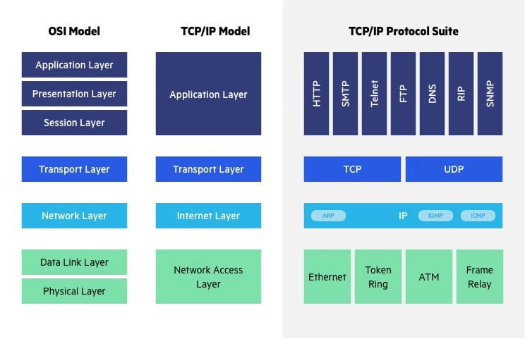 The salient differences between the OSI and TCP/IP models are summarised in Table 1 below.
References
| ||||||||||||||||||||||||||||
MITRE ATT&CK | ||||||||||||||||||||||||||||||||||||||||||||||||||||||||||||||||||||||||||||||||||||||||||
|---|---|---|---|---|---|---|---|---|---|---|---|---|---|---|---|---|---|---|---|---|---|---|---|---|---|---|---|---|---|---|---|---|---|---|---|---|---|---|---|---|---|---|---|---|---|---|---|---|---|---|---|---|---|---|---|---|---|---|---|---|---|---|---|---|---|---|---|---|---|---|---|---|---|---|---|---|---|---|---|---|---|---|---|---|---|---|---|---|---|---|
MITRE ATT&CK® is a knowledge base of adversary tactics (capturing “why”) and techniques (capturing “how”) based on real-world observations. There are three versions [SAM+20]: 1️⃣ Enterprise (first published in 2015), 2️⃣ Mobile (first published in 2017), and 3️⃣ Industrial Control System (ICS, first published in 2020). Fig. 1 below shows the fourteen MITRE ATT&CK Enterprise tactics: 
The Mobile tactics and ICS tactics are summarised below. Note a tactic in the Mobile context is not the same as the identically named tactic in the ICS context.
Among the tools that support the ATT&CK framework is MITRE CALDERA™ (source code on GitHub).
A (blurry) demo is available on YouTube: A complementary model to ATT&CK called PRE-ATT&CK was published in 2017 to focus on “left of exploit” behavior [SAM+20]:
ATT&CK is not meant to be exhaustive, because that is the role of MITRE Common Weakness Enumeration (CWE™) and MITRE Common Attack Pattern Enumeration and Classification (CAPEC™) [SAM+20].
References
| ||||||||||||||||||||||||||||||||||||||||||||||||||||||||||||||||||||||||||||||||||||||||||
MITRE ATLAS | ||||||||||
|---|---|---|---|---|---|---|---|---|---|---|
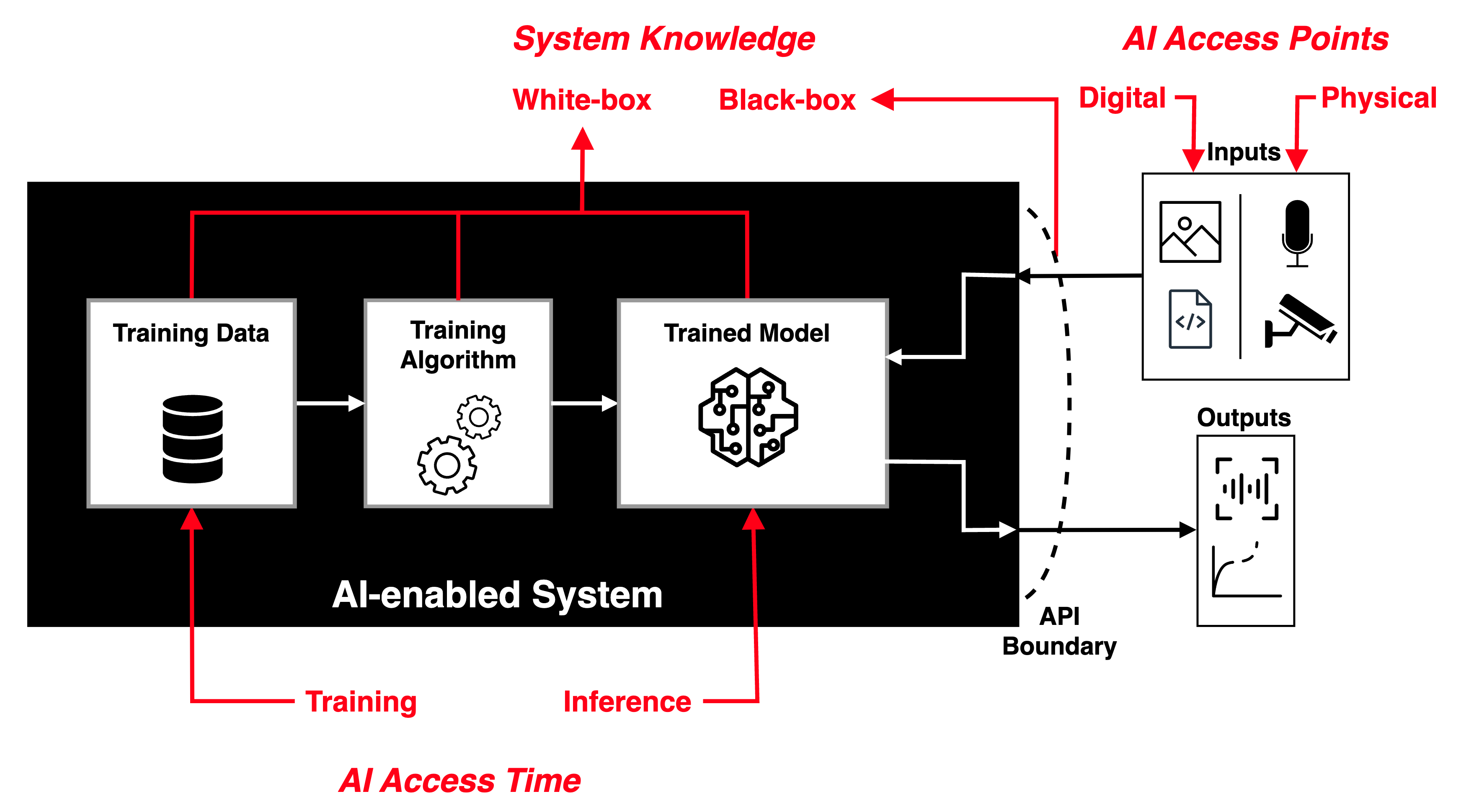
The field of adversarial machine learning (AML) is concerned with the study of attacks on machine learning (ML) algorithms and the design of robust ML algorithms to defend against these attacks [TBH+19, Sec. 1]. ML systems (and by extension AI systems) can fail in many ways, some more obvious than the others. AML is not about ML systems failing when they make wrong inferences; it is about ML systems being tricked into making wrong inferences. Consider three basic attack scenarios on ML systems: Black-box evasion attack: Consider the most common deployment scenario in Fig. 1, where an ML model is deployed as an API endpoint.
White-box evasion attack: Consider the scenario in Fig. 1, where an ML model exists on a smartphone or an IoT edge node, which an adversary has access to.
Poisoning attacks: Consider the scenario in Fig. 1, where an adversary has control over the training data, process and hence the model.
Watch introduction to evasion attacks (informally called “perturbation attacks”) on LinkedIn Learning: Perturbation attacks and AUPs from Security Risks in AI and Machine Learning: Categorizing Attacks and Failure Modes by Diana Kelley Watch introduction to poisoning attacks on LinkedIn Learning: Poisoning attacks from Security Risks in AI and Machine Learning: Categorizing Attacks and Failure Modes by Diana Kelley In response to the threats of AML, in 2020, MITRE and Microsoft, released the Adversarial ML Threat Matrix in collaboration with Bosch, IBM, NVIDIA, Airbus, University of Toronto, etc. Subsequently, in 2021, more organisations joined MITRE and Microsoft to release Version 2.0, and renamed the matrix to MITRE ATLAS (Adversarial Threat Landscape for Artificial-Intelligence Systems). MITRE ATLAS is a knowledge base — modelled after MITRE ATT&CK — of adversary tactics, techniques, and case studies for ML systems based on real-world observations, demonstrations from ML red teams and security groups, and the state of the possible from academic research. Watch MITRE’s presentation: References
| ||||||||||

NIST Cybersecurity Framework | ||||||||||||||||||||||||||||||
|---|---|---|---|---|---|---|---|---|---|---|---|---|---|---|---|---|---|---|---|---|---|---|---|---|---|---|---|---|---|---|
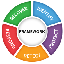
The National Institute of Standards and Technology (NIST) has an essential role in identifying and developing cybersecurity risk frameworks for voluntary use by owners and operators of critical infrastructure (see Definition 1) [NIS18, Executive Summary]. Definition 1: Critical infrastructure [NIS18, Sec. 1.0]
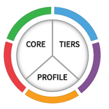
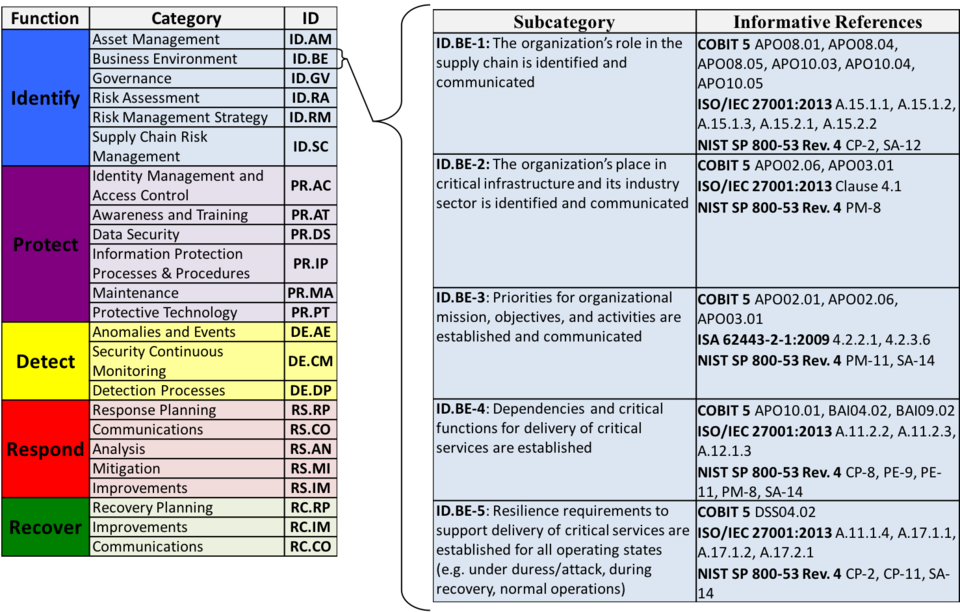
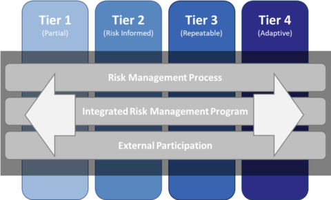
Systems and assets, whether physical or virtual, so vital that the incapacity or destruction of such systems and assets would have a debilitating impact on security, national economic security, national public health or safety, or any combination of those matters. One such framework is the Framework for Improving Critical Infrastructure Cybersecurity (Cybersecurity Framework for short), for which NIST is maintaining an official website. As of writing, the latest version of the NIST Cybersecurity Framework is 1.1 [NIS18]. The Cybersecurity Framework provides a common language for understanding, managing and expressing cybersecurity risks to internal and external stakeholders [NIS18, Sec. 2.0]. The Cybersecurity Framework has three parts: 1️⃣ Framework Core, 2️⃣ Implementation Tiers, and 3️⃣ Framework Profiles.
Watch a more detailed explanation of the Cybersecurity Framework presented at RSA Conference 2018: References
| ||||||||||||||||||||||||||||||

MITRE D3FEND | ||||
|---|---|---|---|---|
MITRE D3FEND is a knowledge base — more precisely a knowledge graph — of cybersecurity countermeasures/techniques, created with the primary goal of helping standardise the vocabulary used to describe defensive cybersecurity functions/technologies.
The D3FEND knowledge graph was designed to map MITRE ATT&CK techniques (or sub-techniques) through digital artefacts to defensive techniques; see Fig. 1.
 Operationally speaking, the D3FEND knowledge graph allows looking up of defence techniques against specific MITRE ATT&CK techniques.
Watch an overview of the D3FEND knowledge graph from MITRE on YouTube: References
| ||||

Systems Security Engineering | ||||||||||||
|---|---|---|---|---|---|---|---|---|---|---|---|---|
NIST provides guidelines on engineering trustworthy (see Definition 1) and cyber-resilient (see Definition 2) systems through NIST SP 800-160 volumes 1 and 2 [RWM22, RPG+21], to be used in conjunction with
Definition 1: Trustworthy [RWM22, p. 1]
Worthy of being trusted to fulfill whatever critical requirements may be needed for a particular component, subsystem, system, network, application, mission, enterprise or other entity. Definition 2: Cyber-resilient [RPG+21, p. 1]
Able to anticipate, withstand, recover from, and adapt to adverse conditions, including stresses, attacks, and compromises on systems that use or are enabled by cyber resources. 📝 A cyber resource is an information resource which creates, stores, processes, manages, transmits, or disposes of information in electronic form and that can be accessed via a network or using networking methods; for example, a file or database. A primary objective of NIST SP 800-160 volume 1 is to provide a basis for establishing a discipline for systems security engineering as part of systems engineering in terms of its principles, concepts, activities and tasks.
 A primary objective of NIST SP 800-160 volume 2 is to provide guidance on how to apply cyber resilience concepts, constructs and engineering practices to systems security engineering and risk management for systems (e.g., enterprise IT, industrial control systems, Internet of Things) and organisations. References
| ||||||||||||
Transport Layer Security | |||
|---|---|---|---|
TODO | |||
Space Attack Research and Tactic Analysis (SPARTA) | ||||||||||||||||||||||||||
|---|---|---|---|---|---|---|---|---|---|---|---|---|---|---|---|---|---|---|---|---|---|---|---|---|---|---|
SPARTA: Space Attack Research and Tactic AnalysisBy The Aerospace Corporation  The Aerospace Corporation created the Space Attack Research and Tactic Analysis (SPARTA) cybersecurity matrix
The SPARTA matrix is a specialisation of the MITRE ATT&CK matrix for defining and categorising commonly identified activities that contribute to spacecraft compromises. The nine SPARTA tactics shown in the top row of Fig. 1 are a subset of the tactics in MITRE ATT&CK.  Under each SPARTA tactic in Fig. 1, each of the main techniques accompanied by a double vertical sign, namely ⏸, can be divided into sub-techniques. For example, under tactic “Reconnaissance” (ST0001), the technique “Gather Spacecraft Design Information” (REC-0001) can be divided into 1️⃣ Software (REC-0001.01), 2️⃣ Firmware (REC-0001.02), 3️⃣ Cryptographic Algorithms (REC-0001.03), 4️⃣ Data Bus (REC-0001.04), 5️⃣ Thermal Control System (REC-0001.05), 6️⃣ Manoeuvre and Control (REC-0001.06), 7️⃣ Payload (REC-0001.07), 8️⃣ Power (REC-0001.08), and 9️⃣ Fault Management (REC-0001.09). Example 1: Payload
The South Australian 6U CubeSat Kanyini has two payloads: 1️⃣ a hyperspectral imager called HyperScout 2 for earth observation, and 2️⃣ an Internet-of-Things communications module. Example 2: Applying SPARTA to modelling a recent cyber attack
Watch a quick overview of the attack called PCspooF: A mixed-criticality system (MCS) is an embedded computing platform in which application functions of different criticalities share computation and/or communication resources [EDN16]. A mixed time-criticality system is an MCS where the criticality is messaging timeliness. Time-Triggered Ethernet (TTEthernet), as standardised in SAE AS6802, defines algorithms for clock synchronisation, clique detection, startup, and restart for switches and end systems to achieve fault-tolerant synchronisation in an Ethernet-based (IEEE 802.3) mixed time-criticality system. TTEthernet is used in avionics, industrial control systems (including those for power systems) and automotive systems [LPDK23], so any security vulnerability in TTEthernet would have wide-reaching consequences.
How TTEthernet works [LPDK23] A TTEthernet network contains two types of devices: switches and end systems. Fault-tolerance is enabled by network redundancy, and each redundant network is called a plane; Fig. 2 shows an example of a system using two planes. Time-triggered (TT) design = All TTEthernet devices are tightly synchronised and the behaviour of the network is determined by a global schedule made offline and loaded onto each TTEthernet device before deployment. 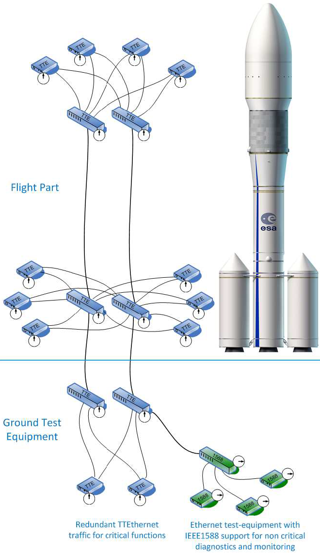 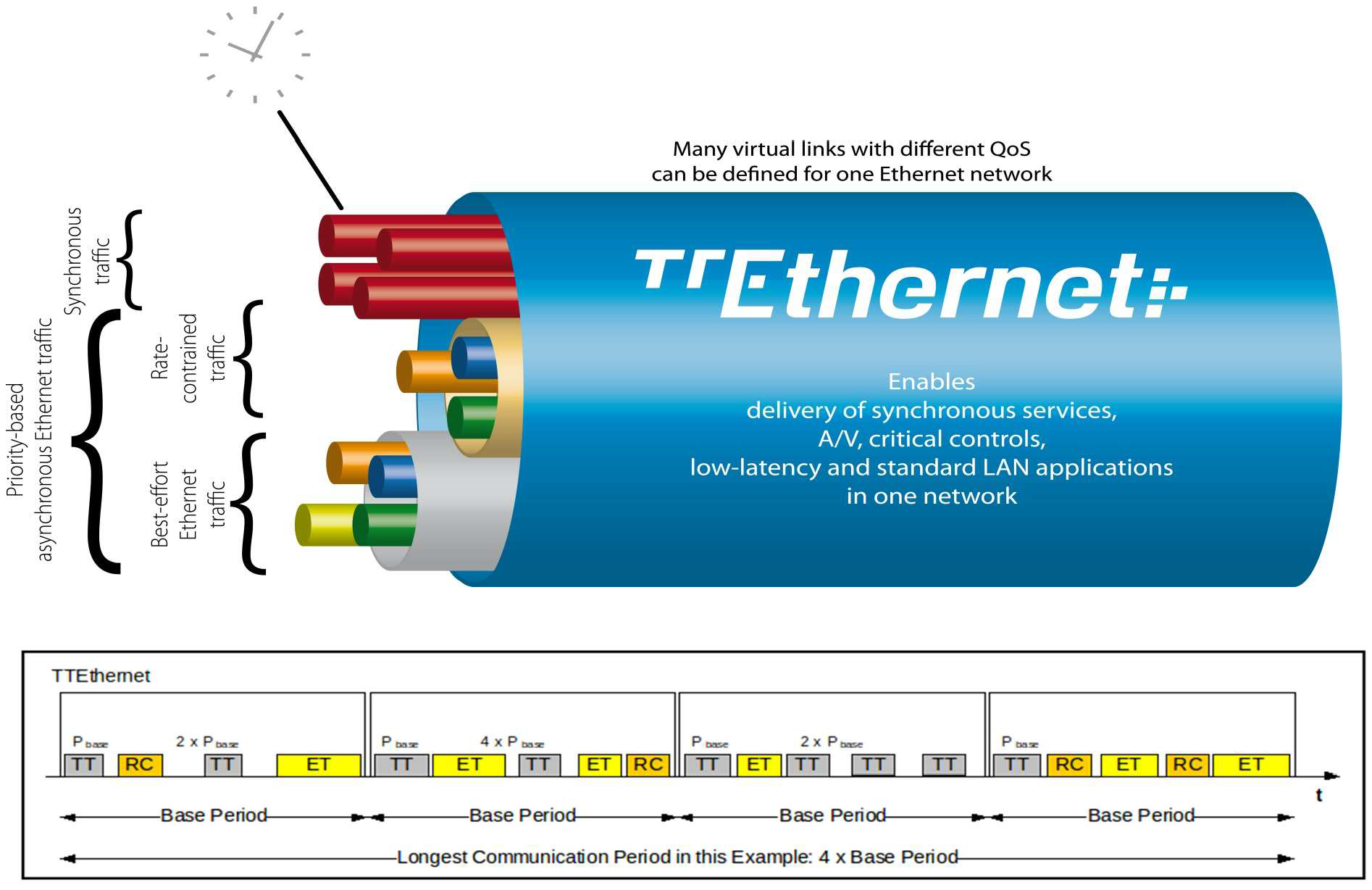 The global schedule specifies when TT frames are forwarded and expected to arrive. The latency and jitter of TT traffic can be reduced to below 13 μs and 1 μs respectively [Fid15, slide 12]. TTEthernet also carries best-effort (BE, i.e., regular) Ethernet traffic and rate-constrained Avionics Full Duplex Switched Ethernet (AFDX, as standardised in ARINC Specification 664 P7-1) traffic; see Fig. 3. TTEthernet switches forward BE traffic around the pre-scheduled TT traffic when bandwidth permits. Mechanisms exist to isolate TT traffic from BE traffic, e.g.,
Central to TTEthernet is a synchronisation protocol, in which a device can participate as 1️⃣ a sync master, 2️⃣ a compression master, or 3️⃣ a sync client.
Devices exchange protocol control frames (PCFs) every integration cycle.
Receiving certain PCFs from a compression master can cause sync masters and clients to lose synchronisation.
Attacker/threat model for PCspooF The PCspooF attack is feasible provided:
  The PCspooF attack PCspooF is a cyber-physical attack that attempts to disrupt the TTEthernet synchronisation protocol by spoofing PCFs, and thereby inflict denial of service on its victim. The attack happens in two stages:
Applying SPARTA Using the language of SPARTA, these attack stages can be identified [The22]: 1️⃣ Reconnaissance, 2️⃣ Resource Development, 3️⃣ Initial Access, 4️⃣ Execution, 5️⃣ Lateral Movement, 6️⃣ Impact Table 1 and Table 2 map these attack stages to the attack steps in PCspooF.
References
| ||||||||||||||||||||||||||


CWE-1189 | |||
|---|---|---|---|
This is a student-friendly explanation of the hardware weakness CWE-1189 “Improper Isolation of Shared Resources on System-on-a-Chip (SoC)”, which is susceptible to
A system-on-a-chip (SoC) may have many functions but a limited number of pins or pads. A pin can only perform one function at a time, but it can be configured to perform multiple functions; this technique is called pin multiplexing. Similarly, multiple resources on the chip may be shared to multiplex and support different features or functions. When such resources are shared between trusted and untrusted agents, untrusted agents may be able to access assets authorised only for trusted agents. Consider the generic SoC architecture in Fig. 1 below:  The SRAM in the hardware root of trust (HRoT) is mapped to the core{0-N} address space accessible by the untrusted part of the system. The HRoT interface (hrot_iface in Fig. 1) mediates access to private memory ranges, allowing the SRAM to function as a mailbox for communication between the trusted and untrusted partitions.
Example 1
An example of CWE-1189 in the real world is CVE-2020-8698 with the description: “Improper isolation of shared resources in some Intel(R) Processors may allow an authenticated user to potentially enable information disclosure via local access”.
🛡 General mitigation
Untrusted agents should not share resources with trusted agents, so when sharing resources, avoid mixing agents of varying trust levels. | |||
CWE-1191 | ||||
|---|---|---|---|---|
This is a student-friendly explanation of the hardware weakness CWE-1191 “On-Chip Debug and Test Interface With Improper Access Control”, which is susceptible to
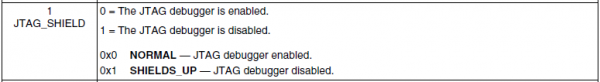
The internal information of a device may be accessed through a scan chain of interconnected internal registers, typically through a Joint Test Action Group (JTAG) interface.
The JTAG interface is so important in the area of hardware security that you should make sure you read the knowledge base entry carefully. Sometimes, designers choose not to expose the debug pins on the motherboard.
Example 1
Barco’s ClickShare family of products is designed to provide end users with wireless presenting capabilities, eliminating the need for wired connections such as HDMI [Wit19]. ClickShare Button R9861500D01 devices, before firmware version 1.9.0, were vulnerable to CVE-2019-18827.
🛡 General mitigation
Disable the JTAG interface or implement access control (at least debug authorisation). Authentication logic, if implemented, should resist timing attacks. Security-sensitive data stored in registers, such as keys, should be cleared when entering debug mode. References
| ||||