Special | A | B | C | D | E | F | G | H | I | J | K | L | M | N | O | P | Q | R | S | T | U | V | W | X | Y | Z | ALL
G |
|---|
Galvanic isolation | ||||||||||||||||||
|---|---|---|---|---|---|---|---|---|---|---|---|---|---|---|---|---|---|---|
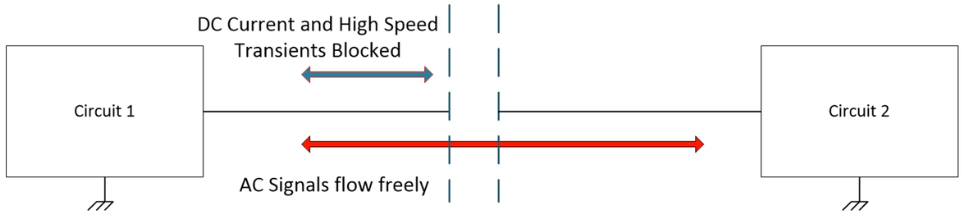
Those who have worked with high-voltage equipment before can readily appreciate the benefits of electrical isolation. When two devices or circuits are in communication, DC currents and AC signals typically flow freely. In low-voltage systems, this is a safe way for two parts of the system to work. However, when high voltage enters into one or more parts of the system, freely-flowing DC current and some AC signals can cause errors, physical damage, and/or create hazardous conditions of operation [Tex20a]. A solution to this problem is galvanic isolation: Definition 1: Galvanic isolation
A means of preventing DC and unwanted AC currents between two parts of a system while still allowing signal and power transfer between those two parts [Tex20a]. Alternative definitions:
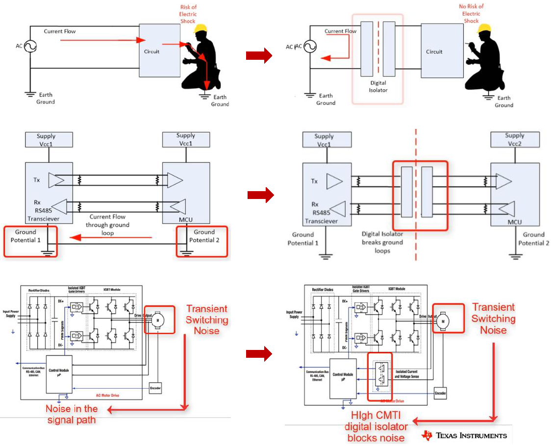
Galvanic isolation can help 1️⃣ protect human operators from electrical shocks, 2️⃣ prevent ground loops, and 3️⃣ improve noise immunity (and thus maintain signal integrity); see Fig. 1. Fig. 1: Sample applications of galvanic isolation. In Fig. 1,
Isolator devices are available in three primary technologies as shown in Fig. 2: 1️⃣ optical, 2️⃣ inductive, and 3️⃣ capacitive. 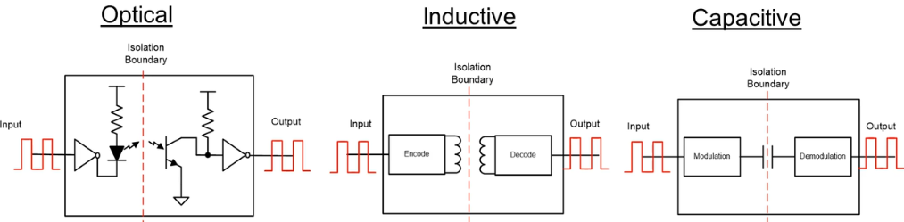 Each technology uses a different insulator material with different dielectric strengths.
Here is how the technologies compare [Sch17, Tex20a]: Optical isolators, also called opto-isolators or optocouplers, typically use air, epoxy or mold compound as the dielectric, which has a low dielectric strength. These isolators have high immunity to electrical and magnetic noise, but their communication rate is limited by LED switching speed. They also suffer from LED aging issues and higher power dissipation than other types of isolators. Inductive/magnetic isolators typically use polyimide as the dielectric, which has a moderate dielectric strength. These isolators enjoy a long lifetime, and their passive barrier can withstand surges/spikes much higher than their continuous voltage rating. However, their inductive coupling via magnetic fields renders them susceptible to magnetic interference. Nevertheless, some new designs manage to certifiably overcome this susceptibility in industry standard tests. Inductive isolation is the oldest among the three technologies. Capacitive isolators typically use SiO2 as the dielectric, which has a high dielectric strength. These isolators have high magnetic immunity, and can support a higher bandwidth than optical isolators. However, their usage of electric fields for data transmission renders them susceptible to electrical interference. Power converters are typically isolated using use either transformer or coupled inductor as shown in Fig. 3.  Besides galvanic isolation, the isolator also serve the purpose of voltage level shifting, or providing multiple outputs [Bla18, Sec. 1.1.1]. However, nonisolated converters are often preferred in applications where galvanic isolation is not a necessity, because they are less bulky, less costly, more efficient and more reliable. Example 1
Here is an example of an isolated DC-DC converter, the 700DNC40-12-xG, from Bel Power Solutions rated at 4 KW, suitable for use in hybrid and electric vehicles: The topic of galvanic isolation can easily occupy an entire course if we really go into the details, but please take advantage of Texas Instruments’ “Introduction to isolation” video series as well as Digi-Key Electronics’ resources [Sch17, Bak18, Pin20]. References
| ||||||||||||||||||