by Yee Wei Law - Thursday, 26 October 2023, 5:47 PM
Acknowledgement: Andrew Edwards contributed some explanation.
Continuing from an overview of BB84, this entry discusses several ways in which BB84 can be realised.
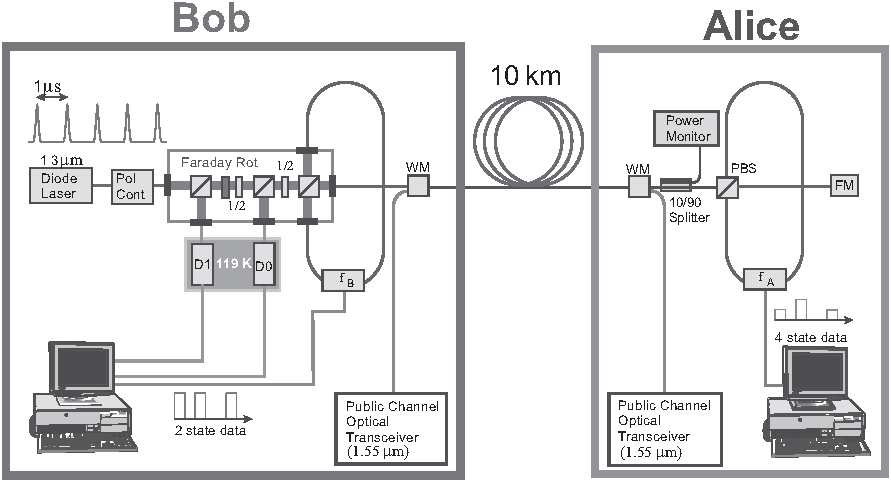
Fig. 1 shows an experimental setup built by IBM [NC10, Box 12.7], where
🧔 Bob generates strong coherent states using a 1.3 μm (near infrared wavelength) diode laser and transmits the states to 👩 Alice 10 km away via an optical fibre.
👩 Alice attenuates the states to generate approximately a single photon, and subsequently polarises the photon to one of , , and .
👩 Alice returns the photon to 🧔 Bob, who measures it using a polarisation analyser in a random basis (either rectilinear or diagonal).
Fig. 1: An experimental setup for BB84 built by IBM [NC10, Box 12.7]. The setup achieved a key bit rate of several hundred bits per second, which is far from practical but it was a start.
For the setup in Fig. 1,
The reason for making the photons traverse the optical fibre twice (from Bob to Alice then back to Bob) is to automatically compensate for asymmetry and fluctuations of the medium.
The polarisation controller (“Pol Cont” in Fig. 1) is for correcting polarisation drifts in the quantum channel [Sud10, p. 111].
The Faraday rotator (“Faraday Rot” in Fig. 1) effects polarisation through the Faraday (rotation) effect; watch demonstration on YouTube.
The classical channel of wavelength 1.55 μm is carried over the same optical fibre. Multiplexing of the quantum and classical channels is achieved through the wavelength (division) multiplexers (“WM” in Fig. 1).
Fig. 2 shows a minimalist block diagram for EDU-QCRY1, while Fig. 3 shows a photo of a physical setup realising the block diagram.
Fig. 2: A minimalist block diagram for Thorlab’s EDU-QCRY1.
Fig. 3: A photo of a physical setup implementing the block diagram in Fig. 2. The silver boxes with a red button are laser electronics. The silver boxes with a green button are sensor electronics. The silver boxes with no button are photon detectors. In EDU-QCRY1, pulsed light sources are used to approximate single-photon sources; see the risk of this approximation in terms of the photon number splitting attack.
Let us study the functions of the PBS in this context:
For Alice to send a to Bob, a half-wave plate (HWP, also called λ/2 plate, labelled as “Polarization Rotator” in Fig. 4) is physically rotated to 0°.
Fig. 4: Transmission from Alice to Bob in the rectilinear basis [Tho20, Figure 2].
To send a , the HWP is physically rotated by 45° to achieve a polarisation rotation of 90°.
In general, for linearly polarised light, polarisation is rotated by a value twice as large as the rotation of the HWP.
On Bob’s side, a horizontally polarised photon () passes through the PBS, while a vertically polarised photon () gets reflected, as shown:
Thus, a single-photon detector is needed to detect each state.
To support both the rectilinear basis (0° and 90°) and diagonal basis (-45° and 45°), the setup in Fig. 4 is extended to the setup in Fig. 6, where Alice’s polarisation rotator now support four angles in total (, , , ), and Bob gets a polarisation rotator that supports two angles (one for each basis).
Fig. 6: Transmission from Alice to Bob in two bases (0° and 90°, -45° and 45°) [Tho20, Figure 3].
Note Bob still needs only two photon detectors, one for each basis state of the selected basis.
Eve can be emulated by simply 1️⃣ duplicating the setup for Bob (for intercepting Alice’s photons), and 2️⃣ duplicating the setup for Alice (for “replaying” measured states to Bob); as shown in Fig. 2.
In recent years, satellite-based experiments on BB84 and extensions of BB84 (e.g., decoy-state BB84) had been conducted [LCPP22].
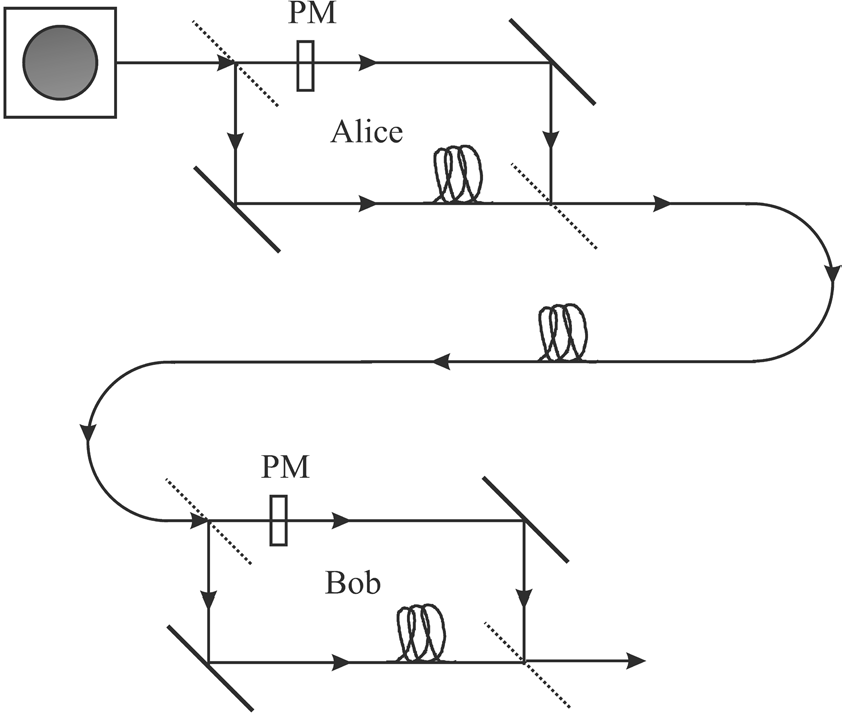
Compared to free space, polarisation is harder to preserve over commercial optical fibres [GK05, Fig. 11.7]. An alternative approach to polarisation is using an interferometer, such as a Mach-Zehnder interferometer; see Fig. 7 and [HIP+21, Sec. 3.2].
Fig. 7: Realising BB84 using an interferometer [GK05, Fig. 11.7]. The shorter and longer paths through the interferometer define the 0 and 1 states. Phase modulators (PM) are positioned within the upper arms of both Bob’s and Alice’s interferometer.
C. Hughes, J. Isaacson, A. Perry, R. F. Sun, and J. Turner, Quantum Computing for the Quantum Curious, Springer Cham, 2021. https://doi.org/10.1007/978-3-030-61601-4.
M. Suda, QKD Systems, in Applied Quantum Cryptography (C. Kollmitzer and M. Pivk, eds.), Lect. Notes Phys.797, Springer Berlin Heidelberg, 2010, pp. 71–95. https://doi.org/10.1007/978-3-642-04831-96.