Browse the glossary using this index

Special | A | B | C | D | E | F | G | H | I | J | K | L | M | N | O | P | Q | R | S | T | U | V | W | X | Y | Z | ALL

Page:  1  2  3  4  5  6  7  8  (Next)
  ALL

2

Picture of Yee Wei Law

2022 cyber threat trends

by Yee Wei Law - Wednesday, 7 June 2023, 1:03 PM
 

Every year, major cybersecurity firms release their report on the trends of cyber threats/attacks they observe during that year.

Some also release their forecast of cybersecurity trends for the next year.

Examples of reports for 2022 are provided in the list of references.

A summary of the trends observed in these reports is provided here, with additional commentary on how some of these attacks happened.

Among the most impactful trends identified [Che22, Cro22b, Man22a, Spl22] are (in no particular order):

  • State-sponsored cyber armies, advanced persistent threats (APTs) and cyberwarfare are on the rise.

    Mandiant has an extensive report [Man22a] on the activities of various threat groups in 2022.

    Threat groups from the “big four” — Russia, China, Iran, North Korea — are expected to be highly active in 2023, using destructive attacks, information operations, financial threats and more [Man22b].

  • Ransomware has been occupying news headlines, and nobody should be a stranger to this escalating threat anymore.

    It is not even farfetched to expect ransomware to be used to attack space systems [Pet22].

  • Macro viruses have existed ever since Microsoft Office started supporting macros.

    They do not seem to be going away.

    Documents containing malicious macros are called “maldoc”, and Emotet (🖱 for details), one of the world’s most prevalent malware (see Fig. 1), has been hailed as the “unofficial king of maldoc usage” [Che22]

Fig. 1: Global ranking of multipurpose malware families in terms of percentage of corporate networks attacked by each malware family [Che22, p. 34].
Fig. 2: Global ranking of cryptomining malware (presumably) in terms of number of infections [Che22, Figure 28].
  • Mobile malware has in recent years started exploiting zero-click vulnerabilities [Jin21], posing tremendous risks to unpatched devices.
  • Cloud-based services are increasingly abused by malicious actors in the course of computer network operations, a trend that is likely to continue in the foreseeable future as more businesses seek hybrid work environments [Cro22b].

    Common cloud attack vectors include cloud vulnerability (e.g., CVE-2021-21972) exploitation, credential theft, cloud service provider abuse, use of cloud services for malware hosting and command & control (C2), and the exploitation of misconfigured Docker containers [Cro22b].

  • In 2021, compromise of cyber supply chain accounted for 17% of intrusions, compared to less than 1% in 2020 [Man22a].

    Furthermore, 86% of these compromises were related to the SolarWinds breach and the SUNBURST malware (trojanised digitally signed component of the SolarWinds Orion software framework that contains a backdoor that communicates via HTTP with third-party servers).

    Watch news report by ABC:

  • An increasing number of malware has cryptocurrency mining (“cryptomining” for short) capabilities [Che22], since these capabilities are readily available in the public domain.

    For example, XMRig is available on GitHub, and is the most popular cryptominer (see Fig. 2).

  • The highest-profile example of attack on cryptocurrency is undoubtedly the “FTX hack”, which allegedly stole USD 415 million from the FTX exchange.

    The attacker had been using crypto laundering services like ChipMixer to launder the stolen funds.

References

[Che22] Check Point, Cyber Attack Trends: Check Point’s 2022 Mid-Year Report, 2022. Available at https://www.checkpoint.com/downloads/resources/cyber-attack-trends-report-mid-year-2022.pdf.
[Cro22b] CrowdStrike, 2022 Global Threat Report, 2022. Available at https://go.crowdstrike.com/global-threat-report-2022.html.
[Jin21] M. Jin, Analyzing The ForcedEntry Zero-Click iPhone Exploit Used By Pegasus, Exploits & Vulnerabilities, September 2021. Available at https://www.trendmicro.com/en_au/research/21/i/analyzing-pegasus-spywares-zero-click-iphone-exploit-forcedentry.html.
[Man22a] Mandiant, M-Trends 2022: Mandiant Special Report, April 2022. Available at https://www.mandiant.com/m-trends.
[Man22b] Mandiant, Mandiant Cyber Security Forecast 2023, November 2022. Available at https://www.mandiant.com/resources/reports/2022/mandiant-security-forecast-2023-predictions.
[Pet22] V. Petkauskas, The ingredients for ransomware attack in space are here - interview, editorial, March 2022. Available at https://cybernews.com/editorial/the-ingredients-for-ransomware-attack-in-space-are-here-interview/.
[Spl22] Splunk, Top 50 Cybersecurity Threats, 2022. Available at https://www.splunk.com/content/dam/splunk2/en_us/gated/ebooks/top-50-cybersecurity-threats.pdf.
Tags:

A

Picture of Yee Wei Law

Abstract interpretation

by Yee Wei Law - Wednesday, 17 May 2023, 10:01 AM
 

High-level overview

Abstract interpretation, first formalised by Cousot and Cousot in 1977 [CC77], executes a program on an abstract machine to determine the properties of interest [vJ11, p. 1255].

The level of detail in the abstract machine specification typically determines the accuracy of the results.

At one end of the spectrum is an abstract machine that faithfully represents the concrete semantics of the language.

Abstract interpretation on such a machine 👆 would correspond to a concrete execution on the real machine.

Typical abstract interpretation analyses, however, do not require detailed semantics.

A bit of theory

Fundamentally, the correctness problem of a program is undecidable, so approximation is necessary [Cou01, Abstract].

The purpose of abstract interpretation is to formalise this idea 👆 of approximation; see Fig. 1.

Formally, abstract interpretation is founded in the theory for approximating sets and set operations [Cou01, Sec. 2].

The semantics of a program can be defined as the solution to a fixpoint (short for fixed point) equation.

Thus, an essential role of abstract interpretation is providing constructive and effective methods for fixpoint approximation and checking by abstraction.

By observing computations at different levels of abstraction (trace semantics → relational semantics → denotational semantics → weakest precondition semantics → Hoare logics), fixpoints can be approximated.

Fig. 1: In abstract interpretation, the program analyzer computes an approximate semantics of the program [Cou01, Fig. 12].

The generator generates equations/constraints, the solution to which is a computer representation of the program semantics.

The solver solves these equations/constraints.

The diagnoser checks the solutions with respect to the specification and outputs “yes”, “no” or “unknown”.

References

[Cou01] P. Cousot, Abstract Interpretation Based Formal Methods and Future Challenges, pp. 138–156, Springer Berlin Heidelberg, Berlin, Heidelberg, 2001. https://doi.org/10.1007/3-540-44577-3_10.
[CC77] P. Cousot and R. Cousot, Abstract interpretation: A unified lattice model for static analysis of programs by construction or approximation of fixpoints, in Proceedings of the 4th ACM SIGACT-SIGPLAN Symposium on Principles of Programming Languages, POPL ’77, Association for Computing Machinery, 1977, pp. 238–252. https://doi.org/10.1145/512950.512973.
[NNH99] F. Nielson, H. R. Nielson, and C. Hankin, Principles of Program Analysis, Springer Berlin, Heidelberg, 1999. https://doi.org/10.1007/978-3-662-03811-6.
[vJ11] H. C. van Tilborg and S. Jajodia (eds.), Encyclopedia of Cryptography and Security, Springer, Boston, MA, 2011. https://doi.org/10.1007/978-1-4419-5906-5.

Picture of Yee Wei Law

Address space layout randomisation (ASLR)

by Yee Wei Law - Tuesday, 16 May 2023, 11:04 AM
 

Address space layout randomisation (ASLR) refers to the randomisation of the locations of the key components of an executable — stack, heap, libraries and memory-mapped files, executable code — in the address space; to mitigate remote code execution and other attacks targeting CWE-787 and CWE-125.

Watch Dr. Yeongjin Jang’s lecture on ASLR:

ASLR targets memory corruption vulnerabilities such as buffer overflows, which typically occur when data get written to memory that is smaller than the size of the data — a common programming error when using a memory-unsafe language like C.

By introducing uncertainty into the locations of the shellcode (or any other attack code), ASLR hinders exploitations of memory corruption vulnerabilities.

There are many ways ASLR can be done, and different operating systems do it differently.

There are three dimensions to be considered [MGRR19]:

When

This is about when the entropy used for ASLR is generated (see Table 1):

  • Per-deployment: The application is randomised when it is installed in the system.

    This limited form of randomisation, called pre-linking, enables randomisation on systems that do not support position-independent code (PIC) or relocatable code.

  • Per-boot: Randomisation is done whenever the system boots.

    Useful for systems whose shared libraries are not compiled as PIC.

  • Per-exec: Randomisation is done whenever a new executable image is loaded into memory.

    This pre-process randomisation is triggered by the exec() system call but not the fork() system call.

  • Per-fork: Randomisation is done whenever a new process is created/forked.

  • Per-object: Every object is randomised when it is created.

    Objects that are at a constant distance away from another already mapped object are not considered to be randomised on a per-object basis, even if the reference object is randomised, because knowledge of one object’s location compromises the location of another.

What

This is about what to randomise.

In the extreme, if a single object (e.g., the executable) is not randomised, ASLR is considered to be broken.

An “aggressive” form of ASLR is when the randomisation is applied to the logical elements contained in the memory objects: processor instructions, blocks of code, functions, and even the data structures of the application; see Table 1.

In this case 👆, the compiler, linker and loader are required to play an active role.

This form of ASLR is not known to be in use.

How

Table 1 lists the main strategies:

  • Partial-VM vs full-VM: In the former case, a subset of the virtual memory space is divided into non-overlapping ranges or zones, and each zone contains one or more objects.

    In the latter case, randomisation applies to the whole virtual memory space.

    Full-VM randomisation does not honour the order of the main areas (i.e., exec, heap, libs, stack, ...), but it is not known to be in use.

  • Isolated-object vs correlated-object: In the former case, every object is randomly mapped with respect to any other.

    In the latter case, the position of an object is calculated as a function of the position of another object and a random value.

  • For details on the other strategies in Table 1, please refer to [MGRR19, pp. 5-6].
Table 1: Summary of the three dimensions of ASLR [MGRR19, Table 1]. vDSO = virtual dynamic shared object; VM = virtual memory.

References

[MGRR19] H. Marco-Gisbert and I. Ripoll Ripoll, Address space layout randomization next generation, Applied Sciences 9 no. 14 (2019). https://doi.org/10.3390/app9142928.

Picture of Yee Wei Law

Advanced persistent threat (APT)

by Yee Wei Law - Thursday, 15 June 2023, 2:54 PM
 

Advanced persistent threat (APT, see Definition 1) has been occupying the attention of many cybersecurity firms.

Definition 1: Advanced persistent threat (APT) [NIS11, Appendix B]

An adversary that possesses sophisticated levels of expertise and significant resources which allow it to create opportunities to achieve its objectives using multiple attack vectors (e.g., cyber, physical, and deception).

These objectives typically include establishing and extending footholds within the information technology infrastructure of the targeted organisations for purposes of exfiltrating information, undermining or impeding critical aspects of a mission, program, or organization; or positioning itself to carry out these objectives in the future.

The advanced persistent threat: 1️⃣ pursues its objectives repeatedly over an extended period of time; 2️⃣ adapts to defenders’ efforts to resist it; and 3️⃣ is determined to maintain the level of interaction needed to execute its objectives.

Since APT groups are characterised by sophistication, persistence and resourcefulness, they are challenging to counter. Lists of APT groups are being actively maintained, e.g., by MITRE and Mandiant.

References

[NIS11] NIST, Managing Information Security Risk: Organization, Mission, and Information System View, NIST Special Publication 800-39, March 2011. Available at https://nvlpubs.nist.gov/nistpubs/legacy/sp/nistspecialpublication800-39.pdf.

Picture of Yee Wei Law

Application security testing

by Yee Wei Law - Sunday, 4 June 2023, 9:42 AM
 

Application security testing can be static or dynamic.

Static application security testing (SAST) is a specialisation of static (code/program) analysis.

Watch an introduction to static code analysis on LinkedIn Learning:

Static analysis from Developing Secure Software by Jungwoo Ryoo

Exploring tools for static analysis from Developing Secure Software by Jungwoo Ryoo

Definitions and history:

  • Static analysis is the processes of extracting semantic information about a program at compile time [Lan92, Sec. 1].
  • Classic example: The live-variables problem, where a variable is live at a statement iff on some execution, is used/accessed after is executed without being redefined [Lan92, Sec. 1; NNH99, p. 49]. This is also an example of data flow analysis (discussed below).
  • In security, static analysis is supposed to classify the potential behaviour of a program as malicious or benign without executing it [vJ11, p. 754].
  • Static analysis algorithms historically have come from compiler research and implementations [vJ11, p. 1254], evolving from intraprocedural analysis to interprocedural analysis [Lan92, Sec. 1].
  • In the 1970s, two main frameworks were established: 1️⃣ data flow analysis, 2️⃣ abstract interpretation. Nowadays, we also have 3️⃣ model checking, and 4️⃣ type checking.

Challenges:

  • Fundamentally, no tool can determine whether a program terminates due to the uncomputability of the halting problem, as we learn from basic complexity theory.

    The halting problem aside, finding an exact solution to typical static analysis questions is almost always undecidable [vJ11, p. 1254].

  • As codebases grow, static analysis tools take longer to parse and traverse code because they generally operate over all possible branches of execution in a program [Tho21].

    Furthermore, static analyses are inherently computationally expensive — often quadratic, sometimes even cubic — in terms of required space or time [Tho21].

    Consequently, static analysis tools are under constant pressure to be more efficient.

  • In general, there exist code obfuscation techniques that can defeat static analysis [MKK07], rendering 1️⃣ static analysis better at finding bugs in benign programs than detecting malware, and 2️⃣ the complementary role of dynamic analysis indispensable.

  • Besides obfuscation, malware often employ polymorphism such as the Shikata Ga Nai polymorphic encoding scheme [MRC19] to deter static analysis [vJ11, p. 754].

Tools:

  • Static analysis is especially important for C/C++ code.

    Among the open-source static analysis tools for C/C++ code, the Clang Static Analyzer and Frama-C offer robust detect rates [ACC+17].

  • For common programming languages, see OWASP’s extensive catalog of static analysis tools.
  • Regardless of the tool used, it helps to write code that facilitates checking, e.g., by adopting Holzman’s power-of-ten rules [Hol06] for writing safety-critical code.

Dynamic application security testing (DAST) is a specialisation of dynamic (code/program) analysis.

Watch an introduction to dynamic code analysis on LinkedIn Learning:

Dynamic analysis from Developing Secure Software by Jungwoo Ryoo

Dynamic analysis tools from Developing Secure Software by Jungwoo Ryoo

Definitions and history:

  • Dynamic analysis refers to the broad class of techniques that make inferences about a program by observing its runtime execution behaviour [vJ11, p. 365].

  • An example of dynamic analysis is fuzz testing, which is the execution of a program-under-test (PUT) using input(s) sampled from an input space (the “fuzz input space”) that “protrudes” the expected input space of the PUT, to test if the PUT violates a correctness policy [MHH+21, Definition 1].
  • Another example of dynamic analysis is taint analysis, also called information flow tracking, which is the tracking of “tainted” data throughout a system while a program manipulating this data is executed [ESKK08].
  • Better than static analysis, dynamic analysis is robust to malware polymorphism, including low-level obfuscations that can thwart disassembly [vJ11, p. 755].
  • Applications: software debugging, software profiling and host-based intrusion detection [vJ11, p. 366].

Challenges:

  • Dynamic analysis tools are typically competent on checking soundness (analysis results are consistent with the actual behaviour of the program), but not so much on completeness (analysis can infer all behaviours of interest of the program).

    In general, static analysis often suffers from a high false-positive rate, whereas dynamic analysis is limited in coverage.

  • There exist anti-emulation techniques that check for certain low-level processor features (e.g., undocumented instructions) or timings, enabling determination of whether the execution environment is an emulation [vJ11, p. 755].

    In case of an emulation, the malware can terminate execution without performing any malicious action and risking detection.

Tools:

  • Among the open-source dynamic analysis tools for C/C++ code, Valgrind [NS07] is likely the best known.
  • For common programming languages, an extensive catalog of dynamic analysis tools can be found on GitHub.

References

[ACC+17] A. Arusoaie, S. Ciobâca, V. Craciun, D. Gavrilut, and D. Lucanu, A Comparison of Open-Source Static Analysis Tools for Vulnerability Detection in C/C++ Code, in 2017 19th International Symposium on Symbolic and Numeric Algorithms for Scientific Computing (SYNASC), 2017, pp. 161–168. https://doi.org/10.1109/SYNASC.2017.00035.
[ESKK08] M. Egele, T. Scholte, E. Kirda, and C. Kruegel, A survey on automated dynamic malware-analysis techniques and tools, ACM Comput. Surv. 44 no. 2 (2008). https://doi.org/10.1145/2089125.2089126.
[Hol06] G. J. Holzmann, The power of 10: rules for developing safety-critical code, Computer 39 no. 6 (2006), 95–99. https://doi.org/10.1109/MC.2006.212.
[Lan92] W. Landi, Undecidability of static analysis, ACM Lett. Program. Lang. Syst. 1 no. 4 (1992), 323 – 337. https://doi.org/10.1145/161494.161501.
[MHH+21] V. J. Manès, H. Han, C. Han, S. K. Cha, M. Egele, E. J. Schwartz, and M. Woo, The art, science, and engineering of fuzzing: A survey, IEEE Transactions on Software Engineering 47 no. 11 (2021), 2312–2331. https://doi.org/10.1109/TSE.2019.2946563.
[MRC19] S. Miller, E. Reese, and N. Carr, Shikata Ga Nai encoder still going strong, Mandiant threat research, 2019. Available at https://www.mandiant.com/resources/blog/shikata-ga-nai-encoder-still-going-strong.
[MKK07] A. Moser, C. Kruegel, and E. Kirda, Limits of static analysis for malware detection, in Twenty-Third Annual Computer Security Applications Conference (ACSAC 2007), 2007, pp. 421–430. https://doi.org/10.1109/ACSAC.2007.21.
[NS07] N. Nethercote and J. Seward, Valgrind: A framework for heavyweight dynamic binary instrumentation, SIGPLAN Not. 42 no. 6 (2007), 89 – 100. https://doi.org/10.1145/1273442.1250746.
[NNH99] F. Nielson, H. R. Nielson, and C. Hankin, Principles of Program Analysis, Springer Berlin, Heidelberg, 1999. https://doi.org/10.1007/978-3-662-03811-6.
[SKK+16] S. Schrittwieser, S. Katzenbeisser, J. Kinder, G. Merzdovnik, and E. Weippl, Protecting software through obfuscation: Can it keep pace with progress in code analysis?, ACM Comput. Surv. 49 no. 1 (2016). https://doi.org/10.1145/2886012.
[Tho21] P. Thomson, Static analysis: An introduction: The fundamental challenge of software engineering is one of complexity, Queue 19 no. 4 (2021), 29 – 41. https://doi.org/10.1145/3487019.3487021.
[vJ11] H. C. van Tilborg and S. Jajodia (eds.), Encyclopedia of Cryptography and Security, Springer, Boston, MA, 2011. https://doi.org/10.1007/978-1-4419-5906-5.
[ZWCX22] X. Zhu, S. Wen, S. Camtepe, and Y. Xiang, Fuzzing: A survey for roadmap, ACM Comput. Surv. 54 no. 11s (2022). https://doi.org/10.1145/3512345.

Picture of Yee Wei Law

Asymmetric-key cryptography

by Yee Wei Law - Friday, 26 May 2023, 11:00 PM
 

Picture of Yee Wei Law

Authenticated encryption with associated data (AEAD)

by Yee Wei Law - Saturday, 19 August 2023, 5:18 PM
 

See 👇 attachment (coming soon) or the latest source on Overleaf.

Tags:

B

Picture of Yee Wei Law

Block ciphers and their modes of operation

by Yee Wei Law - Tuesday, 17 October 2023, 12:06 PM
 
See 👇 attachment or the latest source on Overleaf, for block ciphers and their modes of operation.
Tags:

Picture of Yee Wei Law

Bundle Protocol

by Yee Wei Law - Friday, 8 March 2024, 9:07 AM
 

The original purpose of the delay-tolerant networking (DTN) protocols was to provide space communications scenarios with network-layer functionality similar to that provided by IP-based networks on Earth.

Since space communication scenarios cannot be supported by the terrestrial IP protocol suite, a new solution had to be developed.

The CCSDS Bundle Protocol (BP), based on Bundle Protocol version 6 as defined in RFC 5050 [SB07] and RFC 6260 [Bur11], is meant to provide 1️⃣ basic network-layer functionality, and 2️⃣ storage capability to enable networking benefits even in the presence of delays, disconnections, and rate mismatches [IEH+19].

The latest version of the Bundle Protocol is version 7, as defined in RFC 9171 [BFB22], but this version has yet to be adopted by CCSDS.

For providing integrity and confidentiality services for BP bundles (see Table 1), Bundle Protocol Security (BPSec) is defined in RFC 9172 [BM22].

More concretely, the BP provides network-layer services to applications through these capabilities [CCS15, Secs. 1.1 and 2.1]:

  • custody transfer;
  • coping with intermittent connectivity;
  • taking advantage of scheduled, predicted or opportunistic connectivity (in addition to continuous connectivity);
  • notional data accountability with built-in status reporting;
  • late binding of names to addresses.

When used in conjunction with the Bundle Security Protocol, as defined in RFC 6257 [FWSL11], the BP also provides:

  • hop-by-hop sender authentication; as well as
  • end-to-end data integrity and confidentiality.
Table 1: Bundle Protocol definitions [CCS15, SB07].
Term Definition
Bundle A protocol data unit (PDU) comprising a sequence of two or more blocks of data.
Bundle node An entity that can send and/or receive bundles.
Bundle protocol agent (BPA) A node component that offers the BP services and executes the procedures of the BP.
Convergence layer adapter (CLA)

An adapter that sends and receives bundles on behalf of a BPA.

This is necessary for interoperation with existing Internet protocols; see Fig. 1.

Fig. 1: A sample configuration with the BP and a CLA running over a transport protocol on the left, and over a data link layer on the right [CCS15, Figure 2-1]. The CLA B labelled “CL B” on the right could for instance be the interface to the Licklider Transmission Protocol (LTP) with the “Link B1” representing LTP running over one of the Space Data Link Protocols.

The BP is such an important protocol several open-source implementations exist:

References

[BM22] E. J. Birrane and K. McKeever, Bundle Protocol Security (BPSec), RFC 9172, January 2022. https://doi.org/10.17487/RFC9172.
[Bur11] S. Burleigh, Compressed Bundle Header Encoding (CBHE), RFC 6260, May 2011. https://doi.org/10.17487/RFC6260.
[BFB22] S. Burleigh, K. Fall, and E. J. Birrane, Bundle Protocol Version 7, RFC 9171, January 2022. https://doi.org/10.17487/RFC9171.
[CCS15] CCSDS, CCSDS Bundle Protocol Specification, Recommended Standard CCSDS 734.2-B-1, The Consultative Committee for Space Data Systems, September 2015. Available at https://public.ccsds.org/Pubs/734x2b1.pdf.
[FWSL11] S. Farrell, H. Weiss, S. Symington, and P. Lovell, Bundle Security Protocol Specification, RFC 6257, May 2011. https://doi.org/10.17487/RFC6257.
[IEH+19] D. Israel, B. Edwards, J. Hayes, W. Knopf, A. Robles, and L. Braatz, The Benefits of Delay/Disruption Tolerant Networking (DTN) for Future NASA Science Missions, in 70th International Astronautical Congress (IAC), October 2019. Available at https://ntrs.nasa.gov/citations/20190032313.
[SB07] K. Scott and S. Burleigh, Bundle protocol specification, RFC 5050, November 2007. Available at https://datatracker.ietf.org/doc/rfc5050/.

C

Picture of Yee Wei Law

CCSDS File Delivery Protocol

by Yee Wei Law - Sunday, 21 May 2023, 3:44 PM
 

The CCSDS File Delivery Protocol (CFDP) is standardised in

CFDP has existed for decades, and it is intended to enable packet delivery services in space (space-to-ground, ground-to-space, and space-to-space) environments [CCS20, Sec. 1.1].

CFDP defines 1️⃣ a protocol suitable for the transmission of files to and from spacecraft data storage, and 2️⃣ file management services to allow control over the storage medium [CCS20, Sec. 2.1].

CFDP assumes a virtual filestore and associated services that an implementation must map to the capabilities of the actual underlying filestore used [CCS20, Sec. 1.1].

File transfers can be either unrealiable (class 1) or reliable (class 2):

Class 1 [CCS20, Sec. 7.2]

All file segments are transferred without the possibility of retransmission.

End of file (EOF) is not acknowledged by the receiver.

When the flag Closure Requested is set, the receiver is required to send a Finished PDU upon receiving all file segments (or when the request is cancelled), but the sender does not need to acknowledge the Finished PDU.

The Closure Requested flag is useful when the underlying communication protocol is reliable.

Class 2 [CCS20, Sec. 7.3]

The receiver is required to acknowledge the EOF PDU and the sender has to acknowledge the Finished PDU.

Sending a PDU that requires acknowledgment triggers a timer.

When the timer expires and if the acknowledgment has not been received, the relevant file segment PDU is resent.

This repeats until the ACK Timer Expiration Counter [CCS21b, Sec. 4.4] reaches a predefined maximum value.

Finally, if the counter has reached its maximum value and the acknowledgment has still not been received, a fault condition is triggered which may cause the transfer to be abandoned, canceled or suspended.

The receiver can also indicate missing metadata or data by sending NAK PDUs.

Fig. 2 shows a sample class-2 Copy File transaction between two entities.

Fig. 2: A sample Copy File transaction where an NAK is sent once the (N+1)th File Data PDU is found missing [CCS20, Sec. 3.3]. Additionally, the source user replies with an ACK PDU upon receiving a Finished PDU from the destination user.

Fig. 3 summarises 1️⃣the operation primitives and PDUs in CFDP, as well as 2️⃣ the relationships of these primitives and PDUs to the operational process from initiation through termination.

Fig. 3: An operations view of CFDP: a summary of CFDP operation primitives, PDUs and their relationships to the operational process [CCS21b, Figure 2-1].

Watch an introduction to the CFDP on YouTube:

There are several open-source implementations of CFDP, e.g.,

References

[CCS20] CCSDS, CCSDS File Delivery Protocol (CFDP), Recommended Standard CCSDS 727.0-B-5, The Consultative Committee for Space Data Systems, July 2020. Available at https://public.ccsds.org/Pubs/727x0b5.pdf.
[CCS21a] CCSDS, CCSDS File Delivery Protocol (CFDP) — Part 1: Introduction and Overview, Informational Report CCSDS 720.1-G-4, The Consultative Committee for Space Data Systems, May 2021. Available at https://public.ccsds.org/Pubs/720x1g4.pdf.
[CCS21b] CCSDS, CCSDS File Delivery Protocol (CFDP) — Part 2: Implementers Guide, Informational Report CCSDS 720.2-G-4, The Consultative Committee for Space Data Systems, May 2021. Available at https://public.ccsds.org/Pubs/720x2g4.pdf.

Picture of Yee Wei Law

CCSDS optical communications physical layer

by Yee Wei Law - Saturday, 19 August 2023, 8:10 PM
 
Coming soon.

References

[] .

Picture of Yee Wei Law

CCSDS publications naming convention

by Yee Wei Law - Wednesday, 11 January 2023, 2:51 PM
 

Publications from the Consultative Committee for Space Data Systems (CCSDS) can be found here.

Each publication has an identifier of the form MMM.MM-A-N, where

  • The alphabet A is “B” for blue book (recommended standard), “M” for magenta book (recommended practice), and “G” for green book (informational report).
  • The suffix N is the issue number.

Picture of Yee Wei Law

CCSDS RF communications physical layer

by Yee Wei Law - Friday, 8 March 2024, 3:20 PM
 

The International Telecommunication Union (ITU) has defined a series of regulations or recommendations for space research, space operations and Earth exploration-satellite services [ITU20, Recommendation ITU-R SA.1154-0], but CCSDS has tweaked these recommendations for their purposes [CCS21, Sec. 1.5].

CCSDS has defined two mission categories [CCS21, Sec. 1.5]:

  • Category A for missions having an altitude above the Earth of < 2 million km.
  • Category B for missions having an altitude above the Earth of ≥ 2 million km.

Orthogonal to the preceding classification, CCSDS has also divided their recommendations into these six categories [CCS21, Sec. 2]:

  1. earth-to-space RF
  2. telecommand
  3. space-to-earth RF
  4. telemetry

    Here, “telemetry” encompasses spacecraft housekeeping data and mission data (e.g., video) transmitted from the spacecraft directly to an Earth station or via another spacecraft (space-to-space return link).
  5. radio metric
  6. spacecraft

For example, the recommendations for telemetry RF comm are summarised in Table 1.

Table 1: Telemetry recommendation summary [CCS13a, p. 2.0-5], where NRZ = non-return-to-zero, PCM = pulse code modulation, QPSK = quadrature phase-shift keying,  OQPSK = offset quadrature phase-shift keying, BPSK = binary phase-shift keying, GMSK = Gaussian minimum shift keying, APSK = amplitude and phase-shift keying.

Note:

  • For Category-A missions [CCS21, Sec. 2.4.12A], filtered OQPSK and GMSK modulations are recommended for high-rate telemetry in 1️⃣ the 2-GHz and 8-GHz Space Research bands, 2️⃣ the 8-GHz Earth Exploration-Satellite band, and 3️⃣ the 26-GHz Space Research band.

    Filtered 8PSK modulation is also recommended for the 8-GHz Earth Exploration-Satellite band.

    2 GHz, 8 GHz and 26 GHz are part of the L/S, X and Ka bands respectively.

    This knowledge base entry discusses usage of different frequency bands.

  • For Category-B missions [CCS21, Sec. 2.4.12B], GMSK is recommended for high-rate telemetry in the 2-GHz, 8-GHz and 32-GHz bands.
  • The 25.5–27.0 GHz band (part of K band) is already being used for high-rate transmission in many missions, and usage is expected to rise [CCS21, Sec. 2.4.23].

  • The 32-GHz band (part of Ka band) is planned to become the backbone for communications with high-rate Category-B missions [CCS21, Sec. 2.4.20B].

The Proximity-1 physical layer is separate from all the above.

References

[CCS13a] CCSDS, Proximity-1 Space Link Protocol—Physical Layer, Recommended Standard CCSDS 211.1-B-4, The Consultative Committee for Space Data Systems, December 2013. Available at https://public.ccsds.org/Pubs/211x1b4e1.pdf.
[CCS21] CCSDS, Radio Frequency and Modulation Systems—Part 1 Earth Stations and Spacecraft, Recommended Standard CCSDS 401.0-B-32, The Consultative Committee for Space Data Systems, October 2021. Available at https://public.ccsds.org/Pubs/401x0b32.pdf.
[ITU20] ITU, Radio regulations, 2020. Available at https://www.itu.int/hub/publication/r-reg-rr-2020/.
[McC09] D. McClure, Overview of satellite communications, slides, 2009. Available at https://olli.gmu.edu/docstore/800docs/0909-803-Satcom-course.pdf.

Picture of Yee Wei Law

Complexity theory: first brush

by Yee Wei Law - Friday, 18 August 2023, 12:45 PM
 

See 👇 attachment or the latest source on Overleaf.


Picture of Yee Wei Law

Cryptography: introductory overview

by Yee Wei Law - Friday, 29 March 2024, 12:15 AM
 
See 👇 attachment or the latest source on Overleaf.
Tags:

Picture of Yee Wei Law

CWE-1037

by Yee Wei Law - Wednesday, 29 March 2023, 10:37 AM
 

This is a student-friendly explanation of the hardware weakness CWE-1037 “Processor Optimization Removal or Modification of Security-critical Code”, which is susceptible to

  • CAPEC-663 “Exploitation of Transient Instruction Execution”

While increasingly many security mechanisms have been baked into software, the processors themselves are optimising the execution of the programs such that these mechanisms become ineffective.

Example 1

The most high-profile exploits are known as Meltdown and Spectre (🖱 click links for details).

🛡 General mitigation

Software fixes exist but are partial as the use of speculative execution remains a favourable way of increasing processor performance.

Fortunately, the likelihood of successful exploitation is considered to be low.

References

[KHF+20] P. Kocher, J. Horn, A. Fogh, D. Genkin, D. Gruss, W. Haas, M. Hamburg, M. Lipp, S. Mangard, T. Prescher, M. Schwarz, and Y. Yarom, Spectre attacks: Exploiting speculative execution, Commun. ACM 63 no. 7 (2020), 93 – 101. https://doi.org/10.1145/3399742.

Picture of Yee Wei Law

CWE-1189

by Yee Wei Law - Wednesday, 29 March 2023, 9:56 AM
 

This is a student-friendly explanation of the hardware weakness CWE-1189 “Improper Isolation of Shared Resources on System-on-a-Chip (SoC)”, which is susceptible to

  • CAPEC-124 “Shared Resource Manipulation”.

A system-on-a-chip (SoC) may have many functions but a limited number of pins or pads.

A pin can only perform one function at a time, but it can be configured to perform multiple functions; this technique is called pin multiplexing.

Similarly, multiple resources on the chip may be shared to multiplex and support different features or functions.

When such resources are shared between trusted and untrusted agents, untrusted agents may be able to access assets authorised only for trusted agents.

Consider the generic SoC architecture in Fig. 1 below:

Fig. 1: A generic SoC architecture. Diagram from MITRE.

The SRAM in the hardware root of trust (HRoT) is mapped to the core{0-N} address space accessible by the untrusted part of the system.

The HRoT interface (hrot_iface in Fig. 1) mediates access to private memory ranges, allowing the SRAM to function as a mailbox for communication between the trusted and untrusted partitions.

  • Assuming a malware resides in the untrusted partition, and has access to the core{0-N} memory map.
  • The malware can read from and write to the mailbox region of the SRAM access-controlled by hrot_iface.
  • Security prohibits information from entering or exiting the mailbox region of the SRAM through hrot_iface when the system is in secure or privileged mode.
Example 1

An example of CWE-1189 in the real world is CVE-2020-8698 with the description: “Improper isolation of shared resources in some Intel(R) Processors may allow an authenticated user to potentially enable information disclosure via local access”.

  • A list of the affected Intel processors is available here.
  • Industrial PCs and CNC devices using the affected Intel processors were naturally affected, e.g., some industrial controllers made by Siemens, which fortunately could be patched by updating the BIOS.
🛡 General mitigation

Untrusted agents should not share resources with trusted agents, so when sharing resources, avoid mixing agents of varying trust levels.


Picture of Yee Wei Law

CWE-1191

by Yee Wei Law - Wednesday, 29 March 2023, 9:57 AM
 

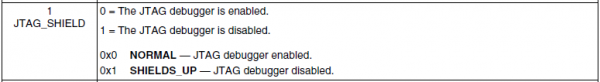
This is a student-friendly explanation of the hardware weakness CWE-1191 “On-Chip Debug and Test Interface With Improper Access Control”, which is susceptible to

  • CAPEC-1 “Accessing Functionality Not Properly Constrained by ACLs” and
  • CAPEC-180 “Exploiting Incorrectly Configured Access Control Security Levels”.

The internal information of a device may be accessed through a scan chain of interconnected internal registers, typically through a Joint Test Action Group (JTAG) interface.

  • The JTAG interface provides access to these registers in a serial fashion in the form of a scan chain for the purposes of debugging programs running on the device.
  • Since almost all information contained within a device may be accessed over this interface, device manufacturers typically implement some form of access control — debug authorisation being the simplest form — in addition to on-chip protections, to prevent unintended use of this sensitive information.
  • If access control is not implemented or not implemented correctly, a user may be able to bypass on-chip protection mechanisms through the debug interface.

The JTAG interface is so important in the area of hardware security that you should make sure you read the knowledge base entry carefully.

Sometimes, designers choose not to expose the debug pins on the motherboard.

  • Instead, they choose to hide these pins in the intermediate layers of the board, to work around the lack of debug authorisation inside the chip.
  • In this scenario (without debug authorisation), when the debug interface is exposed, chip internals become accessible to an attacker.
Example 1

Barco’s ClickShare family of products is designed to provide end users with wireless presenting capabilities, eliminating the need for wired connections such as HDMI [Wit19].

ClickShare Button R9861500D01 devices, before firmware version 1.9.0, were vulnerable to CVE-2019-18827.

  • These devices were equipped with an i.MX28 System-on-Chip (SoC), which in turn was equipped with a JTAG interface for debugging [Wit19].
  • JTAG access protection could be enabled by setting the JTAG_SHIELD bit in the HW_DIGCTRL_CTRL register, which had to be done by an user application, and on system reset, JTAG access became enabled.

  • One way of exploiting this was booting the SoC in the “wait for JTAG” boot mode, where the ROM code entered an infinite loop that could only be broken by manipulating certain registers via JTAG.
  • Therefore on these devices, although JTAG access was disabled after ROM code execution, JTAG access was possible when the system was running code from ROM before handing control over to embedded firmware.
🛡 General mitigation

Disable the JTAG interface or implement access control (at least debug authorisation).

Authentication logic, if implemented, should resist timing attacks.

Security-sensitive data stored in registers, such as keys, should be cleared when entering debug mode.

References

[Wit19] WithSecure Labs, Multiple Vulnerabilities in Barco ClickShare, advisory, 2019. Available at https://labs.withsecure.com/advisories/multiple-vulnerabilities-in-barco-clickshare.

Picture of Yee Wei Law

CWE-125

by Yee Wei Law - Tuesday, 2 May 2023, 5:25 PM
 

This is a student-friendly explanation of the software weakness CWE-125 “Out-of-bounds Read”, where the vulnerable entity reads data past the end, or before the beginning, of the intended buffer. This weakness is susceptible to

This and CWE-787 are two sides of the same coin.

Typically, this weakness allows an attacker to read sensitive information from unexpected memory locations or cause a crash.

Example 1

A high-profile vulnerability is CVE-2014-0160, infamously known as the Heartbleed bug.

Watch an accessible explanation given by Computerphile:

🛡 General mitigation
  • Use a safe programming language that provides appropriate memory abstractions.
  • Assume all inputs are malicious. Where possible, apply the “accept known good” input validation strategy, i.e., use a list of acceptable inputs that strictly conform to specifications; and reject any input that does not strictly conform to specifications, or transform it into something that does.

  • When performing input validation, consider all potentially relevant properties, including length, type of input, the full range of acceptable values, missing or extra inputs, syntax, consistency across related fields, and conformance to business rules.

    Example of business-rule logic: “John” may be syntactically valid because it only contains alphanumeric characters, but it is not valid if the input is only expected to contain colors such as “red” or “blue”.

  • Ensure correct calculation of variables related to length, size, dimension, offset, etc. Be especially cautious of relying on a “sentinel” (e.g., NUL or any other special character) in untrusted inputs.

References

[] .

Picture of Yee Wei Law

CWE-1256

by Yee Wei Law - Saturday, 22 April 2023, 10:52 PM
 

This is a student-friendly explanation of the hardware weakness CWE-1256 “Improper Restriction of Software Interfaces to Hardware Features”, which is susceptible to

Not ready for 2023.


Picture of Yee Wei Law

CWE-1260

by Yee Wei Law - Tuesday, 28 March 2023, 12:46 PM
 

This is a student-friendly explanation of the hardware weakness CWE-1260.

Not ready for 2023.


Picture of Yee Wei Law

CWE-1300

by Yee Wei Law - Sunday, 23 April 2023, 3:02 PM
 

This is a student-friendly explanation of the hardware weakness CWE-1300 “Improper Protection of Physical Side Channels”, which is susceptible to

  • CAPEC-189 “Black Box Reverse Engineering”
  • CAPEC-699 “Eavesdropping on a Monitor”

A hardware product with this weakness does not contain sufficient protection mechanisms to prevent physical side channels from exposing sensitive information due to patterns in physically observable phenomena such as variations in power consumption, electromagnetic emissions (EME), or acoustic emissions.

Example 1

Google’s Titan Security Key is a FIDO universal 2nd-factor (U2F) hardware device that became available since July 2018.

Unfortunately, the security key is susceptible to side-channel attacks observing the local electromagnetic radiations of its secure element — an NXP A700x chip which is now discontinued — during an ECDSA signing operation [RLMI21].

The side-channel attack can clone the secret key in a Titan Security Key.

Watch the USENIX Security ’21 presentation on the side-channel attack:

More examples of side-channel attacks are available here.

🛡 General mitigation

The standard countermeasures are those that apply to CWE-1300 “Improper Protection of Physical Side Channels” and its parent weakness CWE-203 “Observable Discrepancy”.

CWE-1300:

  • Apply blinding or masking techniques to implementations of cryptographic algorithms.
  • Add shielding or tamper-resistant protections to the device to increase the difficulty of obtaining measurements of the side channel.

CWE-203:

  • Compartmentalise the system to have “safe” areas where trust boundaries can be unambiguously drawn.

    Constrain sensitive data to within trust boundaries.

  • Ensure that appropriate compartmentalisation is built into the system design, and the compartmentalisation allows for and reinforces privilege separation functionality.

    Apply the principle of least privilege to decide the appropriate conditions to use or drop privileges.

  • Ensure that error messages only contain minimal details that are useful to the intended audience and no one else.

    The messages should achieve balance between being too cryptic (which can confuse users) and being too detailed (which may reveal more than intended).

    The messages should not reveal the methods used to determine the error because this information can enable attackers to refine or optimise their original attack, thereby increasing their chances of success.

  • If errors must be captured in some detail, record them in log messages not accessible by attackers.

    Highly sensitive information such as passwords should never be saved to log files.

  • Avoid inconsistent messaging that might unintentionally tip off an attacker about internal state, such as whether a user account exists or not.

References

[RLMI21] T. Roche, V. Lomné, C. Mutschler, and L. Imbert, A side journey to titan, in 30th USENIX Security Symposium (USENIX Security 21), USENIX Association, August 2021, pp. 231–248. Available at https://www.usenix.org/conference/usenixsecurity21/presentation/roche.

Picture of Yee Wei Law

CWE-1384

by Yee Wei Law - Wednesday, 26 April 2023, 10:49 AM
 

This is a student-friendly explanation of the hardware weakness CWE-1384 “Improper Handling of Physical or Environmental Conditions”, where a hardware product does not properly handle unexpected physical or environmental conditions that occur naturally or are artificially induced.

This weakness CWE-1384 and the weakness CWE-1300 can be seen as two sides of a coin: while the latter is about leakage of sensitive information, the former is about injection of malicious signals.

Example 1

The GhostTouch attack [WMY+22] generates electromagnetic interference (EMI) signals on the scan-driving-based capacitive touchscreen of a smartphone, which result in “ghostly” touches on the touchscreen; see Fig. 1.

The EMI signals can be generated, for example, using ChipSHOUTER.

Fig. 1: The GhostTouch attack scenario, where the attacker uses an electromagnetic interference (EMI) device under a table to remotely actuate the touchscreen of a smartphone placed face-down on the table [WMY+22, Figure 1].

These ghostly touches enable the attacker to actuate unauthorised taps and swipes on the victim’s touchscreen.

Watch the authors’ presentation at USENIX Security ’22:

PCspooF is another example of an attack exploiting weakness CWE-1384.

🛡 General mitigation

Product specification should include expectations for how the product will perform when it exceeds physical and environmental boundary conditions, e.g., by shutting down.

Where possible, include independent components that can detect excess environmental conditions and are capable of shutting down the product.

Where possible, use shielding or other materials that can increase the adversary’s workload and reduce the likelihood of being able to successfully trigger a security-related failure.

References

[WMY+22] K. Wang, R. Mitev, C. Yan, X. Ji, A.-R. Sadeghi, and W. Xu, GhostTouch: Targeted attacks on touchscreens without physical touch, in 31st USENIX Security Symposium (USENIX Security 22), USENIX Association, Boston, MA, August 2022, pp. 1543–1559. Available at https://www.usenix.org/conference/usenixsecurity22/presentation/wang-kai.

Picture of Yee Wei Law

CWE-787

by Yee Wei Law - Wednesday, 3 May 2023, 9:58 AM
 

This is a student-friendly explanation of the software weakness CWE-787 “Out-of-bounds write”, where the vulnerable entity writes data past the end, or before the beginning, of the intended buffer.

This and CWE-125 are two sides of the same coin.

This can be caused by incorrect pointer arithmetic (see Example 1), accessing invalid pointers due to incomplete initialisation or memory release (see Example 2), etc.

Example 1

In the adjacent C code, char pointer p is allocated only 1 byte, but two bytes away from p, a value of 1 is stored.

Reminder: In a POSIX environment, a C program can be compiled and linked into an executable using command gcc cfilename -o exefilename.

#include <stdlib.h>

int main() {
	char *p;
	p = (char *)malloc(1);
	*(p+2) = 1;
	return 0;
}
Example 2

In the adjacent C code, after the memory allocated to p is freed, p points to a non-existent buffer, but then a value is stored in the nonexistent buffer.

#include <stdlib.h>

int main() {
	char *p;
	p = (char *)malloc(1);
	free(p);
	*p = 1;
	return 0;
}

Typically, the weakness CWE-787 can result in corruption of data, a crash, or code execution.

🛡 General mitigation

A long list of mitigation measures exist, so only a few are mentioned here:

  • Use a safe programming language that does not allow this weakness to occur or provides constructs that make this weakness easier to avoid.

    • For example, many languages that perform their own memory management, such as Java and Perl, are not subject to buffer overflows.
    • Other languages, such as Ada and C# (see Example 3), typically provide overflow protection, but the protection can be disabled by the programmer.
    • Nevertheless, a language’s interface to native code may still be subject to overflows, even if the language itself is theoretically safe.
  • Use a vetted library or framework that is not vulnerable to CWE-787, e.g., Intel’s Safe String Library, and Microsoft’s Strsafe.h library. 👈 These libraries provide safer versions of overflow-prone string-handling functions.
  • Use compilers or compiler extensions that support automatic detection of buffer overflows, e.g., Microsoft Visual Studio with its buffer security check (/GS) flag, the FORTIFY_SOURCE macro on Red Hat Linux platforms, GCC with a range of stack protection flags (that evolved from StackGuard and ProPolice).

Read about more measures here.

Example 3

Using the unsafe keyword, we can write code involving pointers in C#, e.g.,

// compile with: -unsafe
class UnsafeTest
{
    unsafe static void Main()
    {
        int *p; int i = 0;
        p = &i;
        p[2] = 1;
        // Console.WriteLine(p[2]);
    }
}
Fig. 1: Compiling unsafe C# code in Visual Studio 2022.

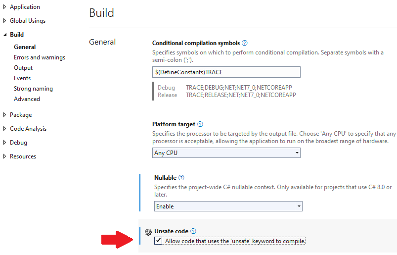
Enabling compilation of unsafe code in Visual Studio as per Fig. 1, the code above can be compiled.

Once compiled and run, the code above will not trigger any runtime error, unless the line writing p[2] to the console is uncommented.

Question: What runtime error would the Console.WriteLine statement in the code above trigger?

References

[] .

Picture of Yee Wei Law

CWE-79

by Yee Wei Law - Wednesday, 3 May 2023, 10:02 AM
 

This is a student-friendly explanation of the software weakness CWE-79 “Improper Neutralization of Input During Web Page Generation ('Cross-site Scripting')”, which is susceptible to

This weakness exists when user-controllable input is not neutralised or is incorrectly neutralised before it is placed in output that is used as a web page that is served to other users.

In general, cross-site scripting (XSS) vulnerabilities occur when:

  • Untrusted data enters a web application, typically through a web request.
  • The web application dynamically generates a web page that contains this untrusted data.
  • During page generation, the application does not prevent the data from containing content that is executable by a web browser, such as JavaScript, HTML tags, HTML attributes, mouse events, etc.
  • A victim visits the generated web page through a web browser, which contains malicious script that was injected using the untrusted data.
  • Since the script comes from a web page that was sent by the web server, the victim’s web browser executes the malicious script in the context of the web server’s domain.
  • This effectively violates the intention of the web browser’s same-origin policy, which states that scripts in one domain should not be able to access resources or run code in a different domain.

Once the malicious script is injected, a variety of attacks are achievable, e.g.,

  • The script could transfer private information (e.g., cookies containing session information) from the victim’s computer to the attacker.
  • The script could send malicious requests to a web site on behalf of the victim, which could be especially dangerous to the site if the victim has administrator privileges to manage that site. Phishing attacks could be used to emulate trusted web sites and trick the victim into entering a password, allowing the attacker to compromise the victim’s account on that web site.
  • The script could exploit a vulnerability of the web browser itself, potentially taking over the victim’s computer. This is known as “drive-by attack”.

The attacks above can usually be launched without alerting the victim.

Even with careful users, URL encoding or Unicode can be used to obfuscate web requests, to make the requests look less suspicious.

Watch an introduction to XSS on LinkedIn Learning:

Understanding cross-site scripting from Security Testing: Vulnerability Management with Nessus by Mike Chapple

Watch a demonstration of XSS on LinkedIn Learning:

Cross-site scripting attacks from Web Security: Same-Origin Policies by Sasha Vodnik

Example 1

The vulnerability CVE-2022-20916 caused the web-based management interface of Cisco IoT Control Center to allow an unauthenticated, remote attacker to conduct an XSS attack against a user of the interface.

The vulnerability was due to absence of proper validation of user-supplied input.

🛡 General mitigation

A long list of mitigation measures exist, so only a few are mentioned here:

  • For any data that will be output to another web page, especially any data that was received from external inputs, use the appropriate encoding on all non-alphanumeric characters (e.g., the symbols “<” and “>”).
  • Use a vetted library or framework implementing defences against XSS, e.g., Microsoft’s Anti-XSS API, the OWASP Enterprise Security API, and Apache Wicket (for Java-based web applications).
  • For any security checks that are performed on the client side, duplicate these checks on the server side, because attackers can bypass client-side checks by modifying values after the checks have been performed, or by changing the client to remove the client-side checks entirely (e.g., using the Web Developer Tools in Firefox).

Read about more measures here and also consult the OWASP Cross Site Scripting Prevention Cheat Sheet.

References

[] .

Picture of Yee Wei Law

CWE-917

by Yee Wei Law - Wednesday, 10 May 2023, 9:24 AM
 

This is a student-friendly explanation of the software weakness CWE-917 “Improper Neutralization of Special Elements used in an Expression Language Statement ('Expression Language Injection')”.

The vulnerable entity constructs all or part of an expression language (EL) statement in a framework such as Jakarta Server Pages (JSP, formerly JavaServer Pages) using externally-influenced input from an upstream component, but it does not neutralise or it incorrectly neutralises special elements that could modify the intended EL statement before it is executed.

  • In the context of JSP, the EL provides a mechanism for enabling the presentation layer (web pages) to communicate with the application logic (managed beans).
  • This weakness is a descendant of CWE-707 “Improper Neutralization”.
Example 1

The infamous vulnerability Log4Shell (CVE-2021-44228) that occupied headlines for months in 2022 cannot be a better example.

Watch an explanation of Log4Shell on YouTube:

🛡 General mitigation

Avoid adding user-controlled data into an expression interpreter.

If user-controlled data must be added to an expression interpreter, one or more of the following should be performed:

  • Ensure no user input will be evaluated as an expression.
  • Encode every user input in such a way that it is never evaluated as an expression.

By default, disable the processing of EL expressions. In JSP, set the attribute isELIgnored for a page to true.

References

[CWE21] CWE/CAPEC, Neutralizing Your Inputs: A Log4Shell Weakness Story, Medium article, December 2021. Available at https://medium.com/@CWE_CAPEC/neutralizing-your-inputs-a-log4shell-weakness-story-89954c8b25c9.

Picture of Yee Wei Law

Cyber Kill Chain

by Yee Wei Law - Wednesday, 15 March 2023, 9:24 AM
 

The Cyber Kill Chain® framework/model was developed by Lockheed Martin as part of their Intelligence Driven Defense® model for identification and prevention of cyber intrusions.

The model identifies what an adversary must complete in order to achieve its objectives.

The seven steps of the Cyber Kill Chain sheds light on an adversary’s tactics, techniques and procedures (TTP):

Watch a quick overview of the Cyber Kill Chain on LinkedIn Learning:

Overview of the cyber kill chain from Ethical Hacking with JavaScript by Emmanuel Henri

Example 1: Modelling Stuxnet with the Cyber Kill Chain

Stuxnet (W32.Stuxnet in Symantec’s naming scheme) was discovered in 2010, with some components being used as early as November 2008 [FMC11].

Stuxnet is a large and complex piece of malware that targets industrial control systems, leveraging multiple zero-day exploits, an advanced Windows rootkit, complex process injection and hooking code, network infection routines, peer-to-peer updates, and a command and control interface [FMC11].

Watch a brief discussion of modelling Stuxnet with the Cyber Kill Chain:

Stuxnet and the kill chain from Practical Cybersecurity for IT Professionals by Malcolm Shore

⚠ Contrary to what the video above claims, Stuxnet does have a command and control routine/interface [FMC11].

References

[FMC11] N. Falliere, L. O. Murchu, and E. Chien, W32.Stuxnet Dossier, Symantec Security Response, February 2011, version 1.4. Available at http://media.kasperskycontenthub.com/wp-content/uploads/sites/43/2014/11/20082206/w32_stuxnet_dossier.pdf.

D

Picture of Yee Wei Law

Data flow analysis

by Yee Wei Law - Sunday, 14 May 2023, 1:19 PM
 

This continues from discussion of application security testing.

Data flow analysis is a static analysis technique for calculating facts of interest at each program point, based on the control flow graph representation of the program [vJ11, p. 1254].

A canonical data flow analysis is reaching definitions analysis [NNH99, Sec. 2.1.2].

For example, if statement is x := y◻z, where is any operator, and x is defined at statement .

Reaching definitions analysis determines for each statement that uses variable x which previous statement defined x.

Example 1 [vJ11, pp. 1254-1255]
In the example below, the definition x at line 1 reaches line 2, but does not reach beyond line 3 because x is assigned on line 3.
1 x := y + z;
2 w := x + z;
3 x := w;

More formally, data flow analysis can be expressed in terms of lattice theory, where facts about a program are modelled as vertices in a lattice.

The lattice meet operator determines how two sets of facts are combined.

Given an analysis where the lattice meet operator is well-defined and the lattice is of finite height, a data flow analysis is guaranteed to terminate and converge to an answer for each statement in the program using a simple iterative algorithm.

A typical application of data flow analysis to security is to determine whether a particular program variable is derived from user input (tainted) or not (untainted).

Given an initial set of variables initialised by user input, data flow analysis can determine (typically an over approximation of) all variables in the program that are derived from user data.

References

[NNH99] F. Nielson, H. R. Nielson, and C. Hankin, Principles of Program Analysis, Springer Berlin, Heidelberg, 1999. https://doi.org/10.1007/978-3-662-03811-6.
[vJ11] H. C. van Tilborg and S. Jajodia (eds.), Encyclopedia of Cryptography and Security, Springer, Boston, MA, 2011. https://doi.org/10.1007/978-1-4419-5906-5.

Picture of Yee Wei Law

Delay-tolerant networking (DTN)

by Yee Wei Law - Monday, 22 May 2023, 10:58 PM
 

In a mobile ad hoc network (MANET, see Definition 1), nodes move around causing connections to form and break over time.

Definition 1: Mobile ad hoc network [PBB+17]

A wireless network that allows easy connection establishment between mobile wireless client devices in the same physical area without the use of an infrastructure device, such as an access point or a base station.

Due to mobility, a node can sometimes find itself devoid of network neighbours. In this case, the node 1️⃣ stores the messages en route to their destination (which is not the node itself), and 2️⃣ when it finds a route of the destination of the messages, forwards the messages to the next node on the route. This networking paradigm is called store-and-forward.

A delay-tolerant networking (DTN) architecture [CBH+07] is a store-and-forward communications architecture in which source nodes send DTN bundles through a network to destination nodes. In a DTN architecture, nodes use the Bundle Protocol (BP) to deliver data across multiple links to the destination nodes.

Watch short animation from NASA:

Watch detailed lecture from NASA:

References

[CCS15] CCSDS, CCSDS Bundle Protocol Specification, Recommended Standard CCSDS 734.2-B-1, The Consultative Committee for Space Data Systems, September 2015.
[CBH+07] V. Cerf, S. Burleigh, A. Hooke, L. Torgerson, R. Durst, K. Scott, K. Fall, and H. Weiss, Delay-tolerant networking architecture, RFC 4838, April 2007.
[IEH+19] D. Israel, B. Edwards, J. Hayes, W. Knopf, A. Robles, and L. Braatz, The Benefits of Delay/Disruption Tolerant Networking (DTN) for Future NASA Science Missions, in 70th International Astronautical Congress (IAC), October 2019. Available at https://www.nasa.gov/sites/default/files/atoms/files/the_benefits_of_dtn_for_future_nasa_science_missions.pdf.
[PBB+17] J. Padgette, J. Bahr, M. Batra, M. Holtmann, R. Smithbey, L. Chen, and K. Scarfone, Guide to Bluetooth Security, NIST Special Publication 800-121 Revision 2 Update 1, May 2017. https://doi.org/10.6028/NIST.SP.800-121r2-upd1.
[SB07] K. Scott and S. Burleigh, Bundle protocol specification, RFC 5050, November 2007.

Picture of Yee Wei Law

Differential power analysis

by Yee Wei Law - Wednesday, 26 April 2023, 9:49 AM
 

Kocher et al. [KJJ99] pioneered the method of differential power analysis (DPA).

A power trace is a set of power consumption measurements taken over a cryptographic operation; see Fig. 1 for an example.

Fig. 1: A sample power trace of a DES encryption [KJJ99, Figure 1], which is clearly indicative of the 16 rounds of the Feistel structure.

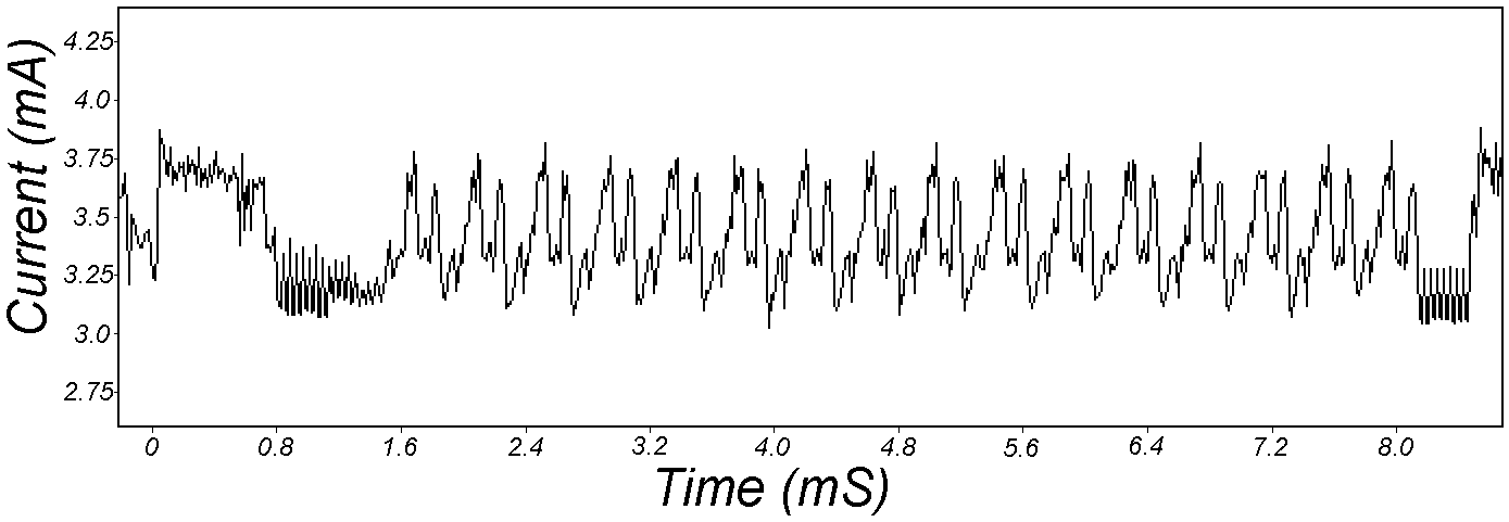
Let us define simple power analysis (SPA) before we get into DPA. SPA is the interpretation of direct power consumption measurements of cryptographic operations like Fig. 1.

Watch a demonstration of SPA:

Most hard-wired hardware implementations of symmetric cryptographic algorithms have sufficiently small power consumption variations that SPA cannot reveal any key bit.

Unlike SPA, DPA is the interpretation of the difference between two sets of power traces.

More precisely, this difference is defined as
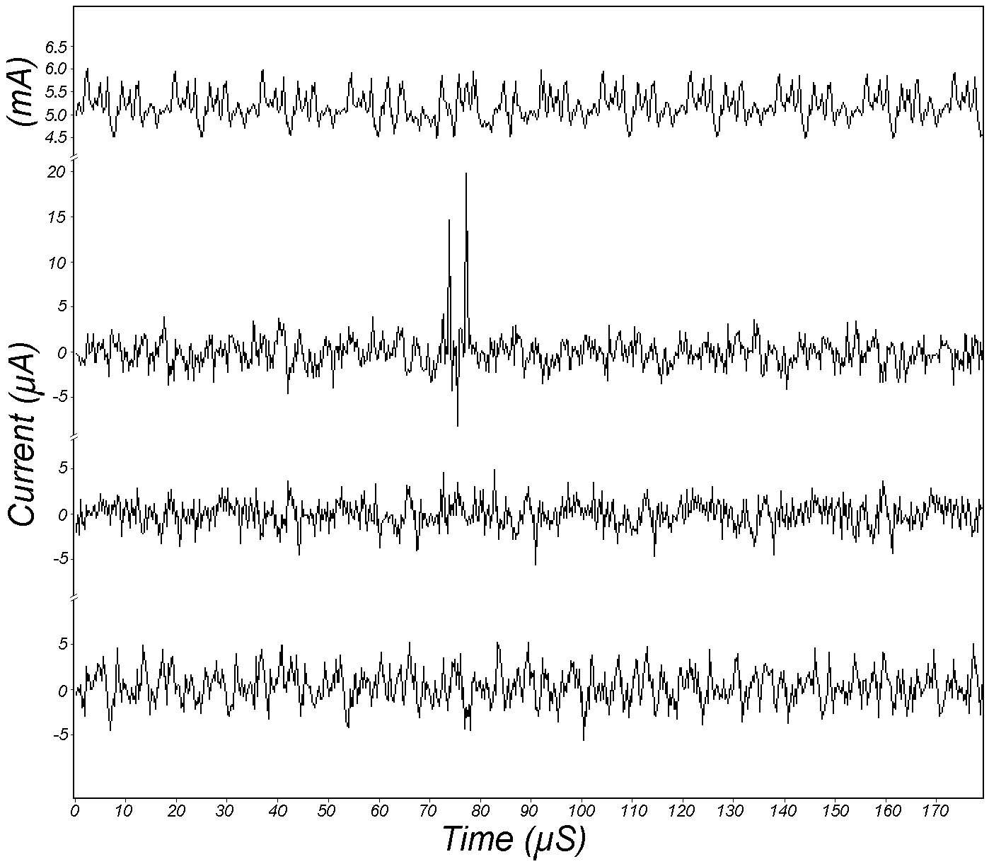
where

  • is the number of traces;
  • is the time index;
  • is the selection function which for the DES (see Figs. 2-3) is defined as the value of bit () of the DES intermediate (see input to block E in Fig. 3) at the beginning of the 16th round for ciphertext when is the 6-bit subkey entering the S-box corresponding to bit ;
  • is the th power trace (vector of power values).

Note each trace is associated with a different ciphertext.

Fig. 2: The Feistel structure of DES, where F denotes the Feistel function (see Fig. 3).

Fig. 3: The Feistel function of DES, where E denotes the expansion permutation that expands a 32-bit input to 48 bits.

During decryption of , denotes the half block (32 bits).

If bit enters S-box S1, then is the 6-bit subkey that enters S-box S1.

DPA was originally devised for DES but it can be adapted to other cryptographic algorithms.

DPA uses power consumption measurements to determine whether a key block guess is correct.

  • There are only possible values of .
  • When the attacker’s guess of is incorrect, the attacker’s value of differs from the actual target bit for about half of the ciphertexts ; equivalently, the selection function is uncorrelated to what was actually computed by the target device, i.e., .
  • When the attacker’s guess of is correct, is correlated to the value of the bit manipulated in the 16th round, i.e.,

    • approaches the effect of the target bit on the power consumption as , where is the time index corresponding to when   is involved in computation;
    • approaches zero for all the times when is not involved in computation.
  • Fig. 4 shows four sample power traces (1 simple, 3 differential).
Fig. 4: From top to bottom: a simple power trace, a differential trace with a spike indicating correct guess, two differential traces for incorrect guesses [KJJ99, Figure 4]. for the differential traces.

References

[KJJ99] P. Kocher, J. Jaffe, and B. Jun, Differential power analysis, in Advances in Cryptology — CRYPTO’ 99 (M. Wiener, ed.), Springer Berlin Heidelberg, Berlin, Heidelberg, 1999, pp. 388–397. https://doi.org/10.1007/3-540-48405-1_25.

Picture of Yee Wei Law

Diffie-Hellman key agreement

by Yee Wei Law - Tuesday, 30 May 2023, 11:21 PM
 

The Diffie-Hellman (D-H) key agreement (often called “key exchange”) protocol is standardised in NIST SP 800-56A [BCR+18].

The protocol originated in the seminal 1976 paper by Whitfield Diffie and Martin Hellman [DH76], both recipients of the 2016 Turing Award (their contribution took 40 years to be recognised).

Protocol between 👩 Alice and 🧔 Bob [KL21, CONSTRUCTION 11.2] in Fig. 1:

  1. On input of security parameter , 👩 Alice runs probabilistic polynomial-time (PPT) algorithm to obtain the domain parameters , where is a cyclic group of prime order , and is a generator of .

    The bit-length of = the security parameter .

    The domain parameters can be pre-distributed.

  2. 👩 Alice chooses , , uniformly at random, and computes .

    is the (cyclic) group of integers modulo .

    👩 Alice’s (ephemeral) private key and public key are and respectively.

  1. 👩 Alice sends to 🧔 Bob.
  2. 🧔 Bob chooses , ,  uniformly at random, and computes .

    🧔 Bob’s (ephemeral) private key and public key are and respectively.

  3. 🧔 Bob sends to 👩 Alice and outputs .
  4. 👩 Alice computes .

Successful completion of the protocol results in the session key .

Fig. 1: The D-H key agreement protocol [KL21, FIGURE 11.2].

A necessary condition for preventing a probabilistic polynomial-time (PPT) eavesdropper from computing the session key is that the computational Diffie-Hellman (CDH) problem is hard:

Definition 1: Computational Diffie-Hellman (CDH) problem [Gal12, Definition 20.2.1]

Given the triple of elements of , compute .

However, the hardness of the CDH problem is not sufficient.

Just as indistinguishability plays an essential role in symmetric-key encryption, indistinguishability is key here: if the session key is indistinguishable from an element chosen uniformly at random from , then we have a sufficient condition for preventing a PPT eavesdropper from computing the session key [KL21, pp. 393-394].

The indistinguishability condition is equivalent to the assumption that the decisional Diffie-Hellman (DDH) problem is hard:

Definition 2: Decisional Diffie-Hellman (DDH) problem [Gal12, Definition 20.2.3]

Given the quadruple of elements of , determine whether or not.

The DDH problem is readily reducible to the CDH problem, since any algorithm that solves the CDH can compute and compare it with ; implying the DDH problem is no harder than the CDH problem.

In turn, the CDH problem is reducible to the discrete logarithm problem (DLP, see Definition 3), since any algorithm that solves the DLP can compute from , from , and hence ; implying the CDH problem is no harder than the DLP problem.

Definition 3: Discrete logarithm problem (DLP) [Gal12, Definition 13.0.1]

Given , where is a multiplicative group, find such that .

In other words, the DDH problem can be reduced to the CDH problem, which in turn can be reduced to the DLP; solving the DLP breaks the D-H key agreement protocol.

There are multiplicative groups for which the DLP is easy, so it is critical that the right groups are used.

A safe-prime group is a cyclic subgroup of the Galois field with prime order , where is called a safe prime; this subgroup has elements [BCR+18, Sec. 5.5.1.1].

NIST [BCR+18, Appendix D] refers to RFC 3526 and RFC 7919 for definitions of safe-prime groups.

The D-H key agreement protocol is used in the Internet Key Exchange (IKE) protocol, which is currently at version 2 [KHN+14].

References

[BCR+18] E. Barker, L. Chen, A. Roginsky, A. Vassilev, and R. Davis, Recommendation for Pair-Wise Key-Establishment Schemes Using Discrete Logarithm Cryptography, Special Publication 800-56A Revision 3, NIST, April 2018. https://doi.org/10.6028/NIST.SP.800-56Ar3.
[DH76] W. Diffie and M. Hellman, New directions in cryptography, IEEE Transactions on Information Theory 22 no. 6 (1976), 644–654. https://doi.org/10.1109/TIT.1976.1055638.
[Gal12] S. D. Galbraith, Mathematics of Public Key Cryptography, Cambridge University Press, 2012. https://doi.org/10.1017/CBO9781139012843.
[KL21] J. Katz and Y. Lindell, Introduction to Modern Cryptography, 3rd ed., CRC Press, 2021. Available at https://ebookcentral.proquest.com/lib/unisa/detail.action?docID=6425020.
[KHN+14] C. Kaufman, P. E. Hoffman, Y. Nir, P. Eronen, and T. Kivinen, Internet Key Exchange Protocol Version 2 (IKEv2), RFC 7296, October 2014. https://doi.org/10.17487/RFC7296.

E

Picture of Yee Wei Law

Emotet

by Yee Wei Law - Tuesday, 9 May 2023, 2:50 PM
 

First identified in 2014 [ANY14], the Emotet malware evolved from a banking Trojan designed to steal sensitive information (including credentials) to a modular, polymorphic, multi-threat downloader for other, more destructive malware [MGB22].

References

[ANY14] ANY.RUN, Emotet, 2014. Available at https://any.run/malware-trends/emotet.
[MGB22] C. Manaster, G. Glass, and E. Biasiotto, Emotet Analysis: New LNKs in the Infection Chain, The Monitor, Issue 20, May 2022. Available at https://www.kroll.com/en/insights/publications/cyber/monitor/emotet-analysis-new-lnk-in-the-infection-chain.

Picture of Yee Wei Law

Encapsulation Packet Protocol (EPP)

by Yee Wei Law - Sunday, 21 May 2023, 7:43 PM
 

The Encapsulation Packet Protocol (EPP) is used to transfer protocol data units (PDUs) recognised by CCSDS that are not directly transferred by the Space Data Link Protocols over an applicable ground-to-space, space-to-ground, or space-to-space communications link [CCS20b].

References

[CCS20b] CCSDS, Encapsulation Packet Protocol, Recommended Standard CCSDS 133.1-B-3, The Consultative Committee for Space Data Systems, May 2020. Available at https://public.ccsds.org/Pubs/133x1b3e1.pdf.

F

Picture of Yee Wei Law

Flow

by Yee Wei Law - Tuesday, 27 June 2023, 4:24 PM
 

A flow is a set of ordered tuples delineated by a start time and an end time, and having the same 1️⃣ session ID, 2️⃣ protocol type, 3️⃣ source and destination IP addresses, as well as 4️⃣ source and destination ports.

References

[] .

H

Picture of Yee Wei Law

Hardware Trojan

by Yee Wei Law - Wednesday, 5 April 2023, 10:46 AM
 

A hardware Trojan (see Definition 1) may control, modify, disable, or monitor the contents and communications of the device it is embedded in [RKK14, Sec. II].

Definition 1: Hardware Trojan [RKK14, BDF+22]

Hardware that has been modified with a malicious functionality hidden from the user.

Hardware Trojans provide a means to bypass traditional software and cryptographic-based protections, allowing a malicious actor to control or manipulate device/system software, 1️⃣ getting access to sensitive information, and/or 2️⃣ causing denial-of-service to legitimate users by causing device/system failures or simply by turning the device/system off [BDF+22].

Examples of hardware Trojans are aplenty within academia and outside of academia [HAT21].

💡 It is easier to produce a proof-of-concept for academic publications or demonstrations than executing a real-world attack that has to be robust to diverse usage scenarios.

👩‍🎓 Examples from within academia

Smartphones often break, but replacing broken components provides an opportunity for malicious actors to implant hardware Trojans.

One of the most frequently replaced components is the touchscreen; more than 50% of smartphone owners have damaged their screen at least once [SCSO17].

Steps of the “Shattered Trust” attack [SCSO17]:

  1. A Trojan screen with an embedded microcontroller is installed.
  2. Rogue microcontroller downloads and installs a Trojan app from the Google Play store 🎦.
  3. Trojan app exploits the buffer flow vulnerability CVE-2017-0650 of the Synaptics S3718 device driver, elevating its own privileges to root, disabling SELinux protection and exfiltrating user data including authentication tokens 🎦.
  4. Attacker creates a remote root shell (through ncat for example) to the compromised phone 🎦.

Another frequently replaced component is the phone battery [LFH+18] 🎦.

On a larger scale, computer peripherals can serve as hardware Trojans that exploit the vulnerabilities in Input-Output Memory Management Units (IOMMUs) [MRG+19].

  • An IOMMU is an MMU component that connects a DMA-capable I/O bus to system memory, and maps device-visible virtual addresses to physical addresses; see Fig. 1.
Fig. 1: The IOMMU translates I/O virtual addresses to physical addresses and applies access control, similar to how the MMU translates virtual addresses from processes [MRG+19, Fig. 2].

Watch Christof Paar’s overview lecture:
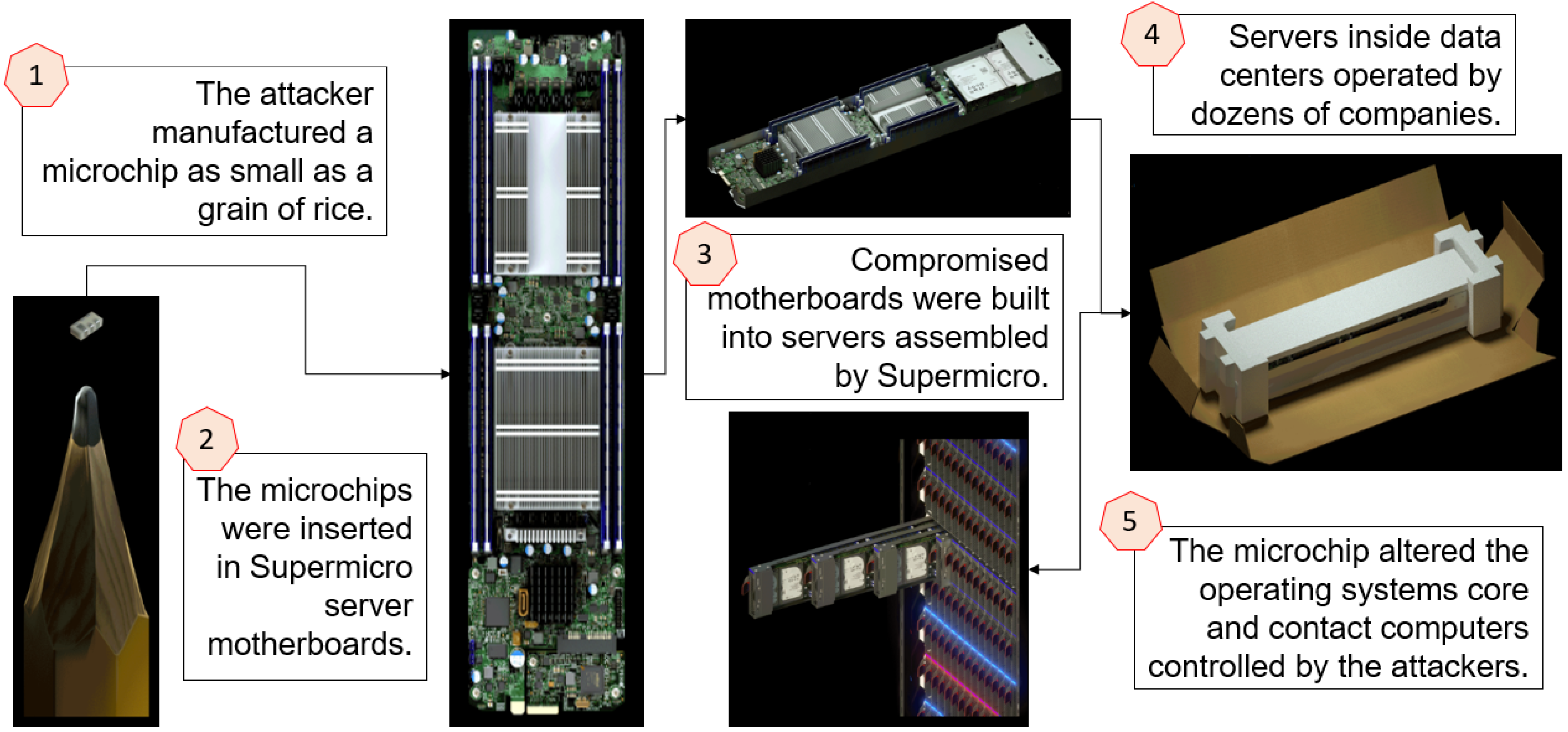
👩‍💻 Examples from outside academia

In 2018, Bloomberg Businessweek made the sensational claim entitled “The Big Hack” that China’s PLA launched a supply chain attack by implanting a tiny Trojan chip in motherboards made by Super Micro Computer Inc. (“Supermicro” for short)  [MLP+20] 🎦.

  • Supermicro specialises in servers, storage, networking devices, and server management software for data centers and cloud computing.
  • Supermicro motherboards were manufactured by contractors in China, facilitating The Big Hack; see Fig. 2. Supermicro now manufactures motherboards for the US market in the US.
Fig. 2: Alleged steps of The Big Hack [MLP+20, Fig. 3].
  • Elemental Technologies (now AWS Elemental, “Elemental” for short) specialised in developing software to compress large video files (e.g., from the International Space Station, from drones) into formats suitable for handheld devices. This technology attracted partnership from the CIA and Amazon.
  • Elemental used Supermicro’s servers in their data centres.
  • Amazon used Supermicro’s servers in their China-based data centres.
  • Amazon’s security team discovered Trojan chips embedded in the fibreglass layers (upon which other components were attached) with access to the baseboard management controller (BMC), which is the component that enables remote administration.
  • X-ray images captured by Amazon’s security team revealed variations in Trojan chip design, but all resemble signal conditioning couplers.
  • The code in the Trojan chips was small, but it could execute two major tasks: 1️⃣ command the motherboard to communicate with external computers, and 2️⃣ command the operating system to accept new code from said computers.
  • Initial Bloomberg report was met with scepticism, but proofs-of-concept started surfacing soon after.

Trojan detection is challenging because [RKK14, Sec. II]:

  1. The inherent opaqueness of device internals hampers detection of modified components. Reverse engineering is typically resource-intensive and in the worst case destructive.
  2. Technology scaling to the limits of device physics and mask imprecisions cause nondeterminism in a device’s characteristics, rendering distinction between process variations and Trojans challenging.
  3. The infeasibility of characterising the entire behavioural space of a device permits  stealthy implantation of Trojans.

Countermeasures

Four main defence strategies can be identified [HAT21, Sec. 4]:

  1. Design for security: Integrating security right from the beginning is a no-brainer. Three main strategies are identifiable:

    • Secure inter-component communications: While it is impractical to demand all inter-component communications to be encrypted and authenticated, critical processes such as booting should be locked down.

      For example, OpenBMC is a Linux distribution for BMCs used in servers, top-of-rack switches, etc. Since the early 2020s, OpenBMC has been supporting secure boot 🎦.

    • Secure test infrastructure: Lock down the JTAG interface to mitigate the risks of attackers accessing sensitive information and/or compromising system functionality.

      Practicality necessitates a lightweight cryptographic protocol (not TLS). Physical unclonable functions (PUFs) provide a lightweight authentication mechanism.

    • Obfuscation and anti-reverse engineering: Attackers need to understand how a device works before they can implant their hardware Trojan.

      Professional attackers resort to a wide range of reverse engineering techniques [FSK+17, SLP+19]:

      A professional foundry attacker has full knowledge of the circuit layout and hence can extract the transistor-level design directly.

      A professional end-user attacker can de-package, de-layer and image an IC, as per Fig. 3. Further processing of these images can facilitate the reconstruction of the circuit layout.

      The process of layout reconstruction and netlist extraction is referred to as physical reverse engineering.

      Fig. 3: Physical reverse engineering flow: an attacker can de-package, de-layer an IC, and leverage image processing techniques to reconstruct the circuit layout [SLP+19, Fig. 2]. The gate-level netlist can subsequently be extracted.

      Reverse engineering also facilitates IP theft.

      Anti-reverse engineering (anti-RE) techniques include [SLP+19, PP20, HAT21]:

      At the very least, use 1️⃣ more routing layers (especially for sensitive signals) in internal PCB layers, 2️⃣ ICs with ball-grid-array connections, and 3️⃣ extraneous traces, vias and components to confuse adversaries.

      Split manufacturing: Front End of Line (FEOL) layers (transistors and lower metal layers) are fabricated at an untrusted high-end foundry, while the Back End of Line (BEOL) layers (higher metal layers) are manufactured at a trusted low-end foundry; see Fig. 4. This approach hides the BEOL connections from the untrusted foundry.

      IC camouflaging: Using fabrication-level techniques to build circuits whose functionality cannot be easily deduced using nanoscale microscopy and other known physical reverse engineering techniques; see Fig. 5.

      Logic locking: Adding some form of programmability to the design and ensuring that the circuit cannot function properly without the circuit being programmed with a secret string of configuration data referred to as the “key”; see Fig. 5.

      Both IC camouflaging and logic locking are examples of logic obfuscation.

      Fig. 4: Vertical structure of a sample IC showing metal layers (M1 to MX), and vias (V1 to VX-1) connecting adjacent metal layers [PP20, Figure 2]. FEOL layers contain transistors, fabrication of which require a high-end foundry.

      Fig. 5: Examples of logic obfuscation [SLP+19, Fig. 1]: (a) IC camouflaging, where a camouflaging cell that from the top view appears to implement either a NAND or a NOR gate as a substitute for the original gate ; (b) logic locking, where correct key bit at is required to unlock gate . While a key bit has only two possible values, many key bits distributed throughout a circuit can constitute a key of a significant size.

      IC camouflaging requires the fixed obfuscated layout structure to be disclosed to the foundry for fabrication, so IC camouflaging only applies to end-user adversaries.

  2. Manufacturing tests: PCB manufacturers have traditionally relied on electrical, functional, and automated optical testing for quality control.

    While manufacturing tests may detect Trojans with payloads that resemble defects, they are not generally useful for detecting modifications by intelligent adversaries.

    Optical inspection of PCBs uses computer vision and machine learning techniques to identify manufacturing defects on both bare-boards and PCB assemblies:

    • Optical inspection machines are commercially available today, complete with proprietary algorithms that are well-tuned to identifying specific board-level defects such as solder bridging or component misalignment.
    • More advanced optical inspection systems use multiple cameras to construct 3D images of boards to identify problems like lifted leads.
    • X-ray solutions have also been developed to enable inspection of inner-layers of PCB routing.
    • While traditional inspection algorithms are well-tuned to identify defects, these algorithms are not adaptable to identifying Trojan modifications.
    • Developing algorithms suitable for PCB assurance is nontrivial.
  3. Board-level Trojan detection: Going beyond manufacturing tests, specific Trojan detection techniques include:

    • Offline side-channel verification: Similar to ICs, circuit boards have unique signatures that depend on the implemented circuit as well as manufacturing variations.

      Malicious modification to PCB substrate, routing, or components could disrupt these side-channel fingerprints.

      Side-channel disruptions such as resonant frequency and delay patterns of PCB traces can be measured either statically or at run time to identify modified or counterfeit PCBs.

    • Advanced optical inspection: This combines information from multiple imaging modalities to verify components and identify illegitimate modifications.

      Imaging modalities can be classified as per Fig. 6.

      Multi-modal optical inspection is a potentially powerful tool for PCB assurance, and research is evolving quickly.

      Not included in Fig. 6 is quantum diamond microscopy [ATW+22]; see Figs. 7-8.

      Fig. 6: Classification of optical testing methods in terms of imaging modality [HAT21, Fig. 4].
      Fig. 7: Workflow and experimental setup [ATW+22, Fig. 3]: (a) Pseudo-flowchart of a QDM magnetic imaging experiment for Trojan detection. (b) Schematic of the experimental components, where a nitrogen-vacancy diamond is placed directly on a field-programmable gate array (FPGA) containing hardware Trojans at the register transfer level. A 532-nm laser is shone at the diamond at a shallow angle and the resultant red fluorescence is captured on a CMOS camera. The nitrogen vacancies are controlled through the application of external microwaves (MW) and a DC bias magnetic field.
      Fig. 8: The “Neural Network Analysis” block in Fig. 7 can be instantiated as a convolutional autoencoder to perform clustering of image features, for the detection of Trojans [ATW+22, Fig. 1].
  4. Run-time monitoring: Run-time monitoring employs additional hardware to ensure device security in the field.

    • Run-time side-channel verification: Side-channel information such as power consumption of clusters of authentic components on a PCB relative to the total power consumed by the PCB can serve as an indicator of Trojan activity — specifically discrepancies outside a certain tolerance might be worth flagging.

    • Policy engines: A policy engine is an IP block that 1️⃣ monitors bus traffic, 2️⃣ searches for traffic that violates a pre-determined rule or model, and 3️⃣ in case of violation, raises an alert or takes a corrective action.

      On PCBs, a policy engine chip can be installed on buses like PCI and I2C to identify denial-of-service attacks or illegitimate messages.

      For example, the validation tool called ConFirm in Fig. 9 performs computational path analysis with hardware performance counters (HPCs), which are special-purpose registers built into the performance monitoring unit of a modern microprocessor for storing information about hardware events [WKMK15].

      Fig. 9: High-level structure of ConFirm [WKMK15, Fig. 2]. The ConFirm core consists of three components in write-protected non-volatile memory: 1️⃣ an insertion module that inserts checkpoints into the monitored firmware, 2️⃣ an HPC handler that drives the HPCs, and 3️⃣ a database that stores valid HPC-based signatures.

      When an execution checkpoint is reached, the control flow is redirected to the core module. The HPC handler compares the event counts for the previous check window with the corresponding signatures in the database. The HPCs are then reset for the next check window and the execution of the monitored firmware continues until the next checkpoint is reached.

      Fig. 10: Computational path analysis with HPCs [WKMK15, Fig. 1]. The execution of the valid paths and in a monitored subroutine generates HPC vectors and encoding occurrence counts of hardware events. A malicious execution could for example go through path , generating an aberrant vector that is distinguishable from and .

      ARM V8 Cortex-A53 for example has 4 HPCs, and can count 62 types of events.

References

[ATW+22] M. Ashok, M. J. Turner, R. L. Walsworth, E. V. Levine, and A. P. Chandrakasan, Hardware trojan detection using unsupervised deep learning on quantum diamond microscope magnetic field images, J. Emerg. Technol. Comput. Syst. 18 no. 4 (2022). https://doi.org/10.1145/3531010.
[BDF+22] J. C. Booth, M. L. Dowell, A. D. Feldman, P. D. Hale, M. M. Midzor, and N. D. Orloff, 5G Hardware Supply Chain Security Through Physical Measurements, NIST Special Publication 1278, May 2022. https://doi.org/10.6028/NIST.SP.1278.
[FSK+17] M. Fyrbiak, S. Strauß, C. Kison, S. Wallat, M. Elson, N. Rummel, and C. Paar, Hardware reverse engineering: Overview and open challenges, in 2017 IEEE 2nd International Verification and Security Workshop (IVSW), 2017, pp. 88–94. https://doi.org/10.1109/IVSW.2017.8031550.
[HAT21] J. Harrison, N. Asadizanjani, and M. Tehranipoor, On malicious implants in PCBs throughout the supply chain, Integration 79 (2021), 12–22. https://doi.org/10.1016/j.vlsi.2021.03.002.
[LFH+18] P. Lifshits, R. Forte, Y. Hoshen, M. Halpern, M. Philipose, M. Tiwari, and M. Silberstein, Power to peep-all: Inference attacks by malicious batteries on mobile devices, in Proc. Priv. Enhancing Technol., 2018, 2018, pp. 141–158. https://doi.org/10.1515/popets-2018-0036.
[MRG+19] A. T. Markettos, C. Rothwell, B. F. Gutstein, A. Pearce, P. G. Neumann, S. W. Moore, and R. N. M. Watson, Thunderclap: Exploring vulnerabilities in operating system IOMMU protection via DMA from untrustworthy peripherals, in Proceedings of the Network and Distributed Systems Security Symposium (NDSS), February 2019, more information at http://thunderclap.io/. Available at https://www.ndss-symposium.org/wp-content/uploads/2019/02/ndss2019_05A-1_Markettos_paper.pdf.
[MLP+20] D. Mehta, H. Lu, O. P. Paradis, M. A. M. S., M. T. Rahman, Y. Iskander, P. Chawla, D. L. Woodard, M. Tehranipoor, and N. Asadizanjani, The Big Hack Explained: Detection and Prevention of PCB Supply Chain Implants, J. Emerg. Technol. Comput. Syst. 16 no. 4 (2020). https://doi.org/10.1145/3401980.
[PP20] T. D. Perez and S. Pagliarini, A survey on split manufacturing: Attacks, defenses, and challenges, IEEE Access 8 (2020), 184013–184035. https://doi.org/10.1109/ACCESS.2020.3029339.
[RKK14] M. Rostami, F. Koushanfar, and R. Karri, A primer on hardware security: Models, methods, and metrics, Proceedings of the IEEE 102 no. 8 (2014), 1283–1295. https://doi.org/10.1109/JPROC.2014.2335155.
[SLP+19] K. Shamsi, M. Li, K. Plaks, S. Fazzari, D. Z. Pan, and Y. Jin, Ip protection and supply chain security through logic obfuscation: A systematic overview, ACM Trans. Des. Autom. Electron. Syst. 24 no. 6 (2019). https://doi.org/10.1145/3342099.
[SCSO17] O. Shwartz, A. Cohen, A. Shabtai, and Y. Oren, Shattered trust: When replacement smartphone components attack, in 11th USENIX Workshop on Offensive Technologies (WOOT), 2017. Available at https://www.usenix.org/system/files/conference/woot17/woot17-paper-shwartz.pdf.
[WKMK15] X. Wang, C. Konstantinou, M. Maniatakos, and R. Karri, ConFirm: Detecting firmware modifications in embedded systems using Hardware Performance Counters, in 2015 IEEE/ACM International Conference on Computer-Aided Design (ICCAD), 2015, pp. 544–551. https://doi.org/10.1109/ICCAD.2015.7372617.

Picture of Yee Wei Law

Hash functions

by Yee Wei Law - Monday, 23 October 2023, 10:29 PM
 
See 👇 attachment or the latest source on Overleaf.
Tags:

Picture of Yee Wei Law

Homodyne vs heterodyne detection

by Yee Wei Law - Wednesday, 8 February 2023, 11:42 AM
 

Homodyne detection = method of detecting a weak frequency-modulated signal through mixing with a strong reference frequency-modulated signal (so-called local oscillator).

References

[ETS18] ETSI, Quantum Key Distribution (QKD); Vocabulary, Group Report ETSI GR QKD 007 v1.1.1, December 2018. Available at https://www.etsi.org/deliver/etsi_gr/QKD/001_099/007/01.01.01_60/gr_qkd007v010101p.pdf.

I

Picture of Yee Wei Law

Intrusion detection: an introduction

by Yee Wei Law - Wednesday, 14 June 2023, 3:57 PM
 

NIST defines intrusion detection to be:

Definition 1: Intrusion detection [SM07, Appendix A]

The process of monitoring the events occurring in a computer system or network and analysing them for signs of possible incidents.

Intrusion prevention goes beyond intrusion detection, although “prevention” is strictly speaking an exaggeration:

Definition 2: Intrusion prevention [SM07, Appendix A]

The process of monitoring the events occurring in a computer system or network, analysing them for signs of possible incidents, and attempting to stop detected possible incidents.

In Definition 2, an “attempt” can be sending an alarm to the administrator(s), resetting a network connection, reconfiguring a firewall to block traffic from the source address, etc.

Thus, “intrusion detection and prevention system” (IDPS) is synonymous with “intrusion prevention system” (IPS) [SM07, Appendix A], and is a bit of a redundant term.

Fig. 1 shows an example of a high-end IPS appliance from Cisco.

Fig. 1: A sample IPS appliance from the Cisco Firepower 9300 Series.

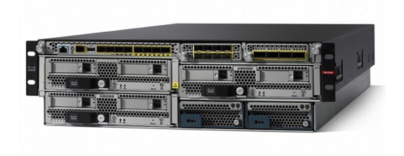
In the 1970s and the early 1980s, administrators had to print out system logs on papers and manually audit the printout [KV02]. The process was clearly 1️⃣ reliant on the auditors’ expertise, 2️⃣ time-consuming, and 3️⃣ too slow to detect attacks in progress.

In the 1980s, storage became cheaper, and intrusion detection programs became available for analysing audit logs online, but the programs could only be run at night when the system’s user load was low [KV02]. Thus, detecting attacks in time remained a challenge.

In the early 1990s, real-time intrusion detection systems (IDSs) that analysed audit logs as the logs were produced became available [KV02].

Since the inception of IDSs, the quality and quantity of audit logs have always been a challenge [KV02]:

Quality

The accuracy (how often the data are correct) and precision (how close the reported values are to the true values) of the data collected are crucial.

Inaccurate or imprecise data could lead to false negatives (illegitimate events misdiagnosed as legitimate) or false positives (legitimate events misdiagnosed as illegitimate).

Quantity

On one hand, not collecting enough data ⇒ an attack could evade detection. For example, network-related data alone cannot help with detecting a malware that does not access any network.

On the other, collecting too much data (from too many sources and/or too frequently) ⇒ storage could run out and processing could take too long.

Effective detection of attacks depends on capturing all relevant data at sufficiently fine time scales.

An IDS is meant to detect [KV02]:

Misuses

These are abuses and attacks of known patterns that can be encoded in computer-interpretable rules or signatures.

An abuse is an intentional or unintentional violation of organisational policies.

Anomalies

An anomaly, also called outlier, is a “significant” deviation from some model of normalcy, where “significance” is contextual and can be fluid.

A model of normalcy is called a baseline model and is often challenging to build for a dynamic environment.

Accordingly, intrusion detection algorithms can be classified as [SM07; YT11, p. 2; BK14, p. 4; Led22; Pal22]:

Rule-based / signature-based

A rule specifies the conditions of legitimacy of an event, typically with the help of signatures.

Signatures can be

  • exploit-facing, e.g., malicious byte sequences, email subject headings associated with phishing, email attachments containing executable binaries, traffic going to known malicious domains, scanning of file hashes; or
  • vulnerability-facing, e.g., SSH requests specifying a vulnerable version number, system log entries indicating disablement of auditing.

Signatures can encode violations of organisational policies, e.g., remote login attempts as “root”.

Stateful protocol analysis or deep packet inspection analyses protocols at the application layer to compare vendor-developed profiles of benign protocol activity against observed events to identify deviations [SH09, Jun16]. This is an example of rule-based detection, contrary to the classification in [LRLT13].

As threats grow, the dictionary of signatures necessarily grows, demanding more computational and storage resources accordingly.

Rule-based detection is effective against known threats that can be expressed using a set of rules and signatures.

Rule-based detection is ineffective against known threats that are hard to capture using a finite set of rules and signatures, e.g., multi-stage attacks; as well as previously unknown threats.

Snort is an industry-standard open-source rule-based intrusion prevention software (hence, also an intrusion detection software). It can for example be found in the appliance in Fig. 1.

Anomaly-based / behaviour-based

This is the application of machine learning techniques to determining whether a user or component behaviour is anomalous.

Depends on the prior establishment of a baseline behavioural model.

Can detect previously unknown attacks as long as the attacks manifest as anomalies relative to the baseline model.

Effective at detection but tends to produce excessive false positives.

Behaviour-based detection, when applied to network behaviour, falls into the area of network behaviour analysis.

Definition 3: Network behaviour analysis [SM07, Xu22]

End-to-end process of collecting, extracting, analysing, modelling, and interpreting network behaviour (e.g., distributed denial of service, worm, backdoor, policy violation) of end systems and network applications from a large volume of network traffic data such as TCP/IP data packets and network flows.

A network behaviour analysis pipeline typically consists of these steps [Xu22, Fig. 2.1]: 1️⃣ network traffic data collection, 2️⃣ data storage and preprocessing, 3️⃣ behavioural feature selection and exploration, 4️⃣ analysis and modeling, 5️⃣ behavioural insights and applications.

Depending on its type, an IDS can comprise several types of components, as shown in Fig. 2: sensors/agents (which monitor and analyse network activities and may also perform preventive actions), management servers, database servers, user and administrator consoles, and management networks [SM07].

There is more than one way to classify IDSs. See the attachment for different classifications of IDSs.

Fig. 2: IDS components. In this context “sensor” is synonymous with “agent”.

Watch the following LinkedIn Learning video for a quick summary of IDS:

What is an IDS? from Protecting Your Network with Open Source Software by Jungwoo Ryoo

References

[BE07] A. R. Baker and J. Esler (eds.), Snort IDS and IPS Toolkit, Syngress, 2007. https://doi.org/10.1016/B978-1-59749-099-3.X5000-9.
[BK14] D. K. Bhattacharyya and J. K. Kalita, Network Anomaly Detection: A Machine Learning Perspective, CRC Press, 2014. https://doi.org/10.1201/b15088.
[FGCMF21] M. Fuentes-García, J. Camacho, and G. Maciá-Fernández, Present and future of network security monitoring, IEEE Access 9 (2021), 112744–112760. https://doi.org/10.1109/ACCESS.2021.3067106.
[Gar22] Gartner, Unified Threat Management (UTM), Information Technology Glossary, 2022, accessed 23 Dec 2022. Available at https://www.gartner.com/en/information-technology/glossary/unified-threat-management-utm.
[HH05] S. Hansman and R. Hunt, A taxonomy of network and computer attacks, Computers & Security 24 no. 1 (2005), 31–43. https://doi.org/10.1016/j.cose.2004.06.011.
[JDR+11] A. Johnson, K. Dempsey, R. Ross, S. Gupta, and D. Bailey, Guide for security-focused configuration management of information systems, NISP Special Publication 800-128, August 2011. https://doi.org/10.6028/NIST.SP.800-128.
[Jun16] Juniper Networks, Learn about intrusion detection and prevention, 2016. Available at https://www.juniper.net/documentation/en_US/learn-about/LA_IntrusionDetectionandPrevention.pdf.
[KV02] R. Kemmerer and G. Vigna, Intrusion detection: a brief history and overview, Computer 35 no. 4 (2002), supl27–supl30. https://doi.org/10.1109/MC.2002.1012428.
[KGVK19] A. Khraisat, I. Gondal, P. Vamplew, and J. Kamruzzaman, Survey of intrusion detection systems: techniques, datasets and challenges, Cybersecurity 2 no. 1 (2019), 20. https://doi.org/10.1186/s42400-019-0038-7.
[Led22] J. Ledesma, IDS vs. IPS: What Organizations Need to Know, Varonis Inside Out Security Blog, June 2022. Available at https://www.varonis.com/blog/ids-vs-ips.
[LRLT13] H.-J. Liao, C.-H. Richard Lin, Y.-C. Lin, and K.-Y. Tung, Intrusion detection system: A comprehensive review, Journal of Network and Computer Applications 36 no. 1 (2013), 16–24. https://doi.org/10.1016/j.jnca.2012.09.004.
[LDVH+18] L. Liu, O. De Vel, Q.-L. Han, J. Zhang, and Y. Xiang, Detecting and preventing cyber insider threats: A survey, IEEE Communications Surveys & Tutorials 20 no. 2 (2018), 1397–1417. https://doi.org/10.1109/COMST.2018.2800740.
[Mav20] N. Mavis, Snort 101, YouTube video by Cisco Talos Intelligence Group, February 2020. Available at https://youtu.be/W1pb9DFCXLw.
[NDP18] J. Navarro, A. Deruyver, and P. Parrend, A systematic survey on multi-step attack detection, Computers & Security 76 (2018), 214–249. https://doi.org/10.1016/j.cose.2018.03.001.
[Pal22] Palo Alto Networks, What is an intrusion prevention system?, Cyberpedia, 2022, accessed 21 Dec 2022. Available at https://www.paloaltonetworks.com/cyberpedia/what-is-an-intrusion-prevention-system-ips.
[SH09] K. Scarfone and P. Hoffman, Guidelines on firewalls and firewall policy, NIST Special Publication 800-41 Revision 1, September 2009. Available at https://nvlpubs.nist.gov/nistpubs/Legacy/SP/nistspecialpublication800-41r1.pdf.
[SM07] K. Scarfone and P. Mell, Guide to Intrusion Detection and Prevention Systems (IDPS), NIST Special Publication 800-94, 2007. Available at https://nvlpubs.nist.gov/nistpubs/Legacy/SP/nistspecialpublication800-94.pdf.
[Sno20] Snort, SNORT® Users Manual 2.9.16, 2020. Available at https://www.snort.org/documents/snort-users-manual-2-9-16-html.
[Sno23] Snort, Shared Object Rules, Snort FAQ, 2023, accessed 3 Feb 2023. Available at https://www.snort.org/faq/shared-object-rules.
[Via22] Viasat, KA-SAT Network cyber attack overview, Viasat corporate news, March 2022. Available at https://news.viasat.com/blog/corporate/ka-sat-network-cyber-attack-overview.
[Xu22] K. Xu, Network Behavior Analysis: Measurement, Models, and Applications, Springer Singapore, 2022. https://doi.org/10.1007/978-981-16-8325-1.
[YT11] Z. Yu and J. J. Tsai, Intrusion Detection: A Machine Learning Approach, Electrical and Computer Engineering, Imperial College Press, 2011.

Picture of Yee Wei Law

Intrusion detection systems: classifications

by Yee Wei Law - Monday, 27 February 2023, 12:02 PM
 
See attachment 👇.

J

Picture of Yee Wei Law

JTAG

by Yee Wei Law - Wednesday, 29 March 2023, 10:18 AM
 

The increasing usage of cutting-edge technologies in safety-critical applications leads to strict requirements on the detection of defects both at the end of manufacturing and in the field [VDSDN+19].

Besides scan chains, test access ports (TAPs) and associated protocols constitute the fundamental test mechanism [VDSDN+19].

Among the earliest standards for test access ports is IEEE Std 1149.1a-1993, first drafted by the Joint Test Action Group (JTAG) in the late 1980s, and then standardised by the IEEE in the early 1990s [IEEE13].

  • The most recent edition of the standard is the 444 pages-long IEEE Std 1149.1-2013 [IEEE13].
  • This standard defines a test access port and boundary scan architecture for 1️⃣ digital integrated circuits and for 2️⃣ the digital portions of mixed analog/digital integrated circuits.
  • The architecture of boundary scan in Fig. 1 is responsible for controlling scan chains through a JTAG interface and an embedded hardware module [BT19, Sec. 3.6.3].
  • The technique of boundary scan involves the inclusion of a shift-register stage (contained in a boundary-scan register cell, see Fig. 2) adjacent to each component pin so that signals at component boundaries can be controlled and observed using scan testing principles [IEEE13, Sec. 1.2.3].
  • Instructions (not states) are loaded into the instruction register (IR), and depending on the instruction, a different data register (DR) is connected between the TDI and TDO terminals; for example, the BYPASS instruction connects a single flip-flop between the TDI and TDO ports [VDSDN+19, p. 96].

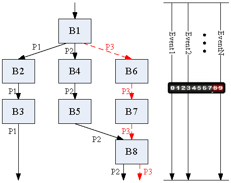
Fig. 1: The boundary scan architecture [BT19, FIGURE 3.19]. Note: TDI = test data input; TMS = test mode select; TCK = test clock input; TRST = test reset; TDO = test data output.

The boundary-scan register cells for the pins of a component are interconnected to form a shift-register chain around the border of the design, and this path is provided with serial input and output connections as well as appropriate clock and control signals [IEEE13, Sec. 1.2.3].

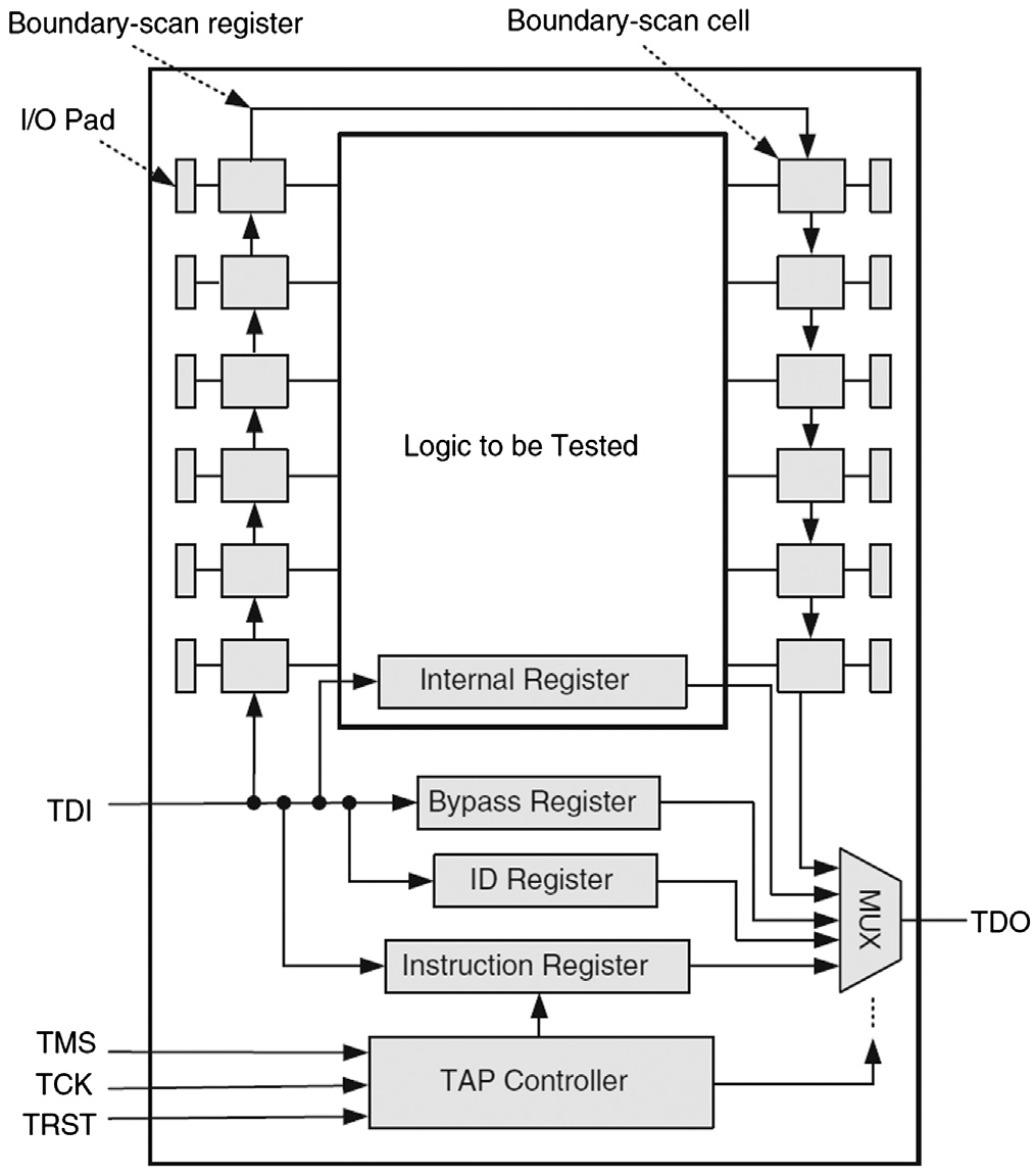
Fig. 2: A sample boundary-scan register cell [IEEE13, Figure 1-1].

If used for an input, data can either be loaded into the scan register from the input pin through the “Signal In” port, or be driven from the register through the “Signal Out” port of the cell into the core of the component design, depending on the control signals applied to the multiplexers (see Fig. 1).

If used for an an output, data can either be loaded into the scan register from the core of the component, or be driven from the register to an output pin.

The TAP controller in Fig. 1 implements the 16-state finite state machine in Fig. 3.

For example, Select-DR-Scan is a temporary controller state (i.e., the next rising edge of TCK makes the controller exit this state) in which all test data registers (DRs) selected by the current instruction retain their previous state [IEEE13, p. 26].

  • If TMS is held low and a rising edge is applied to TCK, the controller enters the Capture-DR state and a scan sequence for the selected test data register is initiated.
  • If TMS is held high and a rising edge is applied to TCK, the controller enters the Select-IR-Scan state.
  • The instruction does not change while the TAP controller is in this state.
Fig. 3: The standard TAP controller state diagram [IEEE13, Figure 6-1].

Operationally speaking, the most important consideration for a security analyst, when assessing the security of a device, is finding a JTAG interface. Standard tools such as the Bus Pirate, JTAGulator and Open On-Chip Debugger (OpenOCD) can then be used to probe the device through this interface.

Watch the following tutorial on YouTube:

References

[BT19] S. Bhunia and M. Tehranipoor, Hardware Security: A Hands-On Learning Approach, Morgan Kaufmann, 2019. https://doi.org/10.1016/C2016-0-03251-5.
[IEEE13] IEEE Computer Society, IEEE Standard for Test Access Port and Boundary-Scan Architecture: IEEE Std 1149.1-2013 (Revision of IEEE Std 1149.1-2001), 2013. https://doi.org/10.1109/IEEESTD.2013.6515989.
[RM19] P. H. N. Rajput and M. Maniatakos, JTAG: A Multifaceted Tool for Cyber Security, in 2019 IEEE 25th International Symposium on On-Line Testing and Robust System Design (IOLTS), 2019, pp. 155–158. https://doi.org/10.1109/IOLTS.2019.8854430.
[RK10] K. Rosenfeld and R. Karri, Attacks and Defenses for JTAG, IEEE Design & Test of Computers 27 no. 1 (2010), 36–47. https://doi.org/10.1109/MDT.2010.9.
[VDSDN+19] E. Valea, M. Da Silva, G. Di Natale, M.-L. Flottes, and B. Rouzeyre, A Survey on Security Threats and Countermeasures in IEEE Test Standards, IEEE Design & Test 36 no. 3 (2019), 95–116. https://doi.org/10.1109/MDAT.2019.2899064.
[VL18] G. Vishwakarma and W. Lee, Exploiting JTAG and Its Mitigation in IOT: A Survey, Future Internet 10 no. 12 (2018). https://doi.org/10.3390/fi10120121.

K

Picture of Yee Wei Law

Key establishment and key management

by Yee Wei Law - Monday, 29 May 2023, 11:39 AM
 

Key establishment (see Definition 1) is part of key management (see Definition 2).

Definition 1: Key establishment [MvV96, Definition 1.63]

A process whereby a shared secret key becomes available to two or more parties, for subsequent cryptographic use.

Definition 2: Key management [BB19, p. 12]

Activities involved in the handling of cryptographic keys and other related parameters (e.g., IVs and domain parameters) during the entire life cycle of the keys, including their generation, storage, establishment, entry and output into cryptographic modules, use and destruction.

Simply speaking, key management is a set of processes and mechanisms which support key establishment and the maintenance of ongoing keying relationships between parties, including replacing older keys with new keys as necessary [MvV96, Definition 1.64]; see Fig. 1.

Fig. 1: Key lifecycle in key management [SC16, Figure 2.18]. The events are self-explanatory.
Example 1

Key management includes identification of the key types.

CCSDS [CCS11] has identified the following key types for securing space missions:

  • Long-term data encryption keys: These are symmetric keys for protecting the confidentiality of data over long time periods.

    These keys require confidentiality and integrity protection, and must remain available and associated with the encrypted data or services as long as the data encrypted under these keys is maintained in its encrypted form.

  • Short-term data encryption keys: These are symmetric keys for protecting the confidentiality of data over short time periods, e.g., over a communication session.

    These short-term keys are generated as needed.

    The confidentiality and integrity of these keys must be maintained until the entire session has been decrypted.

    Upon the conclusion of a session, these short-term keys must be securely destroyed.

  • Key transport public keys: These keys are used for transporting keying material (e.g., encryption keys, MAC keys, initialisation vectors) in the encrypted form.

    These keys must be validated prior to their use, and retained until no longer needed (e.g., the public/private key pair is replaced, or key transport is no longer required).

  • Key transport private keys: These keys are used for decrypting keying material encrypted with the corresponding public keys.

  • Other key types discussed in [CCS11, Sec. A2].

Key establishment can be broadly classified into key agreement (see Definition 3) and key transport (see Definition 4).

Definition 3: Key agreement [BB19, p. 11]

A pair-wise key-establishment procedure in which the resultant secret keying material is a function of information contributed by both participants, so that neither party can predetermine the value of the secret keying material independently from the contributions of the other party.

👩 ➡ 🔑 ⬅ 🧔

Definition 4: Key transport [BB19, p. 14]

A key-establishment procedure whereby one entity (the sender) selects a value for secret keying material and then securely distributes that value to one or more other entities (the receivers).

👩 ➡ 🔑 ➡ 👨‍👩‍👧‍👦

Key agreement is more popular than key transport, and the de facto standard key agreement protocol is Diffie-Hellman key agreement.

References

[BB19] E. Barker and W. C. Barker, Recommendation for Key Management: Part 2 - Best Practices for Key Management Organizations, Special Publication 800-57 Part 2 Revision 1, NIST, May 2019. https://doi.org/10.6028/NIST.SP.800-57pt2r1.
[CCS11] CCSDS, Space Missions Key Management Concept, Informational Report CCSDS 350.6-G-1, The Consultative Committee for Space Data Systems, November 2011. Available at https://public.ccsds.org/Pubs/350x6g1.pdf.
[MvV96] A. J. Menezes, P. C. van Oorschot, and S. A. Vanstone, Handbook of Applied Cryptography, CRC Press, 1996. Available at https://cacr.uwaterloo.ca/hac/.
[SC16] J. J. Stapleton and W. Clay Epstein, Security without Obscurity: A Guide to PKI Operations, CRC Press, 2016. https://doi.org/10.1201/b19725.

L

Picture of Yee Wei Law

Licklider Transmission Protocol (LTP)

by Yee Wei Law - Friday, 8 March 2024, 11:03 AM
 

CCSDS has adopted the Licklider Transmission Protocol (LTP) as specified in the IETF RFC 5326 [BFR08b] and the associated security extensions specified in IETF RFC 5327 [BFR08a] to provide reliability and authentication mechanisms on top of an underlying (usually data link) communication service [CCS15b, Sec. 1.1].

In an Interplanetary Internet setting deploying the Bundle Protocol [BFR08b], LTP is intended to serve as a reliable “convergence layer” protocol operating in pairwise fashion between adjacent in-range Interplanetary Internet nodes.

LTP aggregates multiple layer-(N+1) PDUs into a single layer-N PDU for reliable delivery — this allows the system to reduce the acknowledgement-channel bandwidth in the case that the layer-(N+1) (and higher) protocols transmit many small PDUs, each of which might otherwise require independent acknowledgement; see Fig. 1.

In CCSDS settings [CCS15b, Sec. 1.2], LTP is intended for use over package delivery services including packet telecommand and packet telemetry.

For space links, LTP is typically deployed over a CCSDS data link that supports CCSDS Encapsulation Packets so that one LPT segment can be encapsulated in a single Encapsulation Packet.

LTP can also operate over ground-network services, in which case it is usually deployed over UDP; see Fig. 2.

Fig. 1: To protocols above LTP (e.g., Bundle Protocol), LTP enables reliable delivery of layer-(N+1) PDUs across a link [CCS15b, Figure 1-1].

For LTP, the interface to the data link is via either direct encapsulation in CCSDS Space Packets or the CCSDS Encapsulation Service.

Fig. 2: A simplified end-to-end view of the system elements involved in a typical Solar System Internetwork (SSI) scenario: a Space User Node, an SSI “cloud”, and an Earth User Node, where the mission operations centre (MOC) is located [CCS13, Figure 3-4].

References

[BFR08a] S. C. Burleigh, S. Farrell, and M. Ramadas, Licklider Transmission Protocol - Security Extensions, RFC 5327, September 2008. https://doi.org/10.17487/RFC5327.
[BFR08b] S. C. Burleigh, S. Farrell, and M. Ramadas, Licklider Transmission Protocol - Specification, RFC 5326, September 2008. https://doi.org/10.17487/RFC5326.
[CCS13] CCSDS, Space Communications Cross Support—Architecture Description Document, Informational Report CCSDS 901.0-G-1, The Consultative Committee for Space Data Systems, November 2013. Available at https://public.ccsds.org/Pubs/901x0g1.pdf.
[CCS15b] CCSDS, Licklider Transmission Protocol (LTP) FOR CCSDS, Recommended Standard CCSDS 734.1-B-1, The Consultative Committee for Space Data Systems, May 2015. Available at https://public.ccsds.org/pubs/734x1b1.pdf.

M

Picture of Yee Wei Law

Meltdown attacks

by Yee Wei Law - Wednesday, 29 March 2023, 8:45 AM
 

Out-of-order execution is a prevalent performance feature of modern processors for reducing latencies of busy execution units, e.g., a memory fetch unit waiting for data from memory: instead of stalling execution, a processor skips ahead and executes subsequent instructions [LSG+18].

See Fig. 1.

Fig. 1: If an executed instruction causes an exception that diverts the control flow to an exception handler, the subsequent instruction must not be executed [LSG+18, Figure 3].

Due to out-of-order execution, the subsequent instructions may already have been partially executed, but not retired.

However, architectural effects of the execution are discarded.

Although the instructions executed out of order do not have any visible architectural effect on the registers or memory, they have microarchitectural side effects [LSG+18, Sec. 3].

  • During out-of-order execution, referenced memory contents are fetched into the registers and also stored in the cache.
  • If the result of out-of-order execution has to be discarded, the register and memory contents are retired, but the cached memory contents are kept in the cache.
  • A microarchitectural side-channel attack such as FLUSH+RELOAD [YF14] can then be exploited to detect whether a specific memory location is cached, to make this microarchitectural state visible.

Meltdown consists of two building blocks [LSG+18, Sec. 4], as illustrated in Fig. 2:

  1. The first building block makes the CPU execute one or more instructions that would never occur in the normal executed path.

    These instructions, which are executed out of order and leaving measurable side effects, are called transient instructions.

  2. The second building block transfers the microarchitectural side effect of the transient instruction sequence to an architectural state to further process the leaked secret.

Operation-wise, Meltdown consists of 3 steps [LSG+18, Sec. 5.1]:

  1. The content of an attacker-chosen memory location, which is inaccessible to the attacker, is loaded into a register.
  2. A transient instruction accesses a cache line based on the secret content of the register; see Fig. 2.
  3. The attacker uses FLUSH+RELOAD to determine the accessed cache line and hence the secret stored at the chosen memory location.

Fig. 2: The Meltdown attack uses exception handling or suppression, e.g., TSX (disabled by default since 2021), to run a series of transient instructions [LSG+18, Figure 5].

The covert channel consists of 1️⃣ transient instructions obtaining a (persistent) secret value and changing the microarchitectural state of the processor based on this secret value; 2️⃣ FLUSH+RELOAD reading the microarchitectural state, making it architectural and recovering the secret value.

Watch the presentation given by one of the discoverers of Meltdown attacks at the 27th USENIX Security Symposium:

Since FLUSH+RELOAD was mentioned, watch the original presentation at USENIX Security ’14:

More information on the Meltdown and Spectre website.

References

[LSG+18] M. Lipp, M. Schwarz, D. Gruss, T. Prescher, W. Haas, A. Fogh, J. Horn, S. Mangard, P. Kocher, D. Genkin, Y. Yarom, and M. Hamburg, Meltdown: Reading kernel memory from user space, in 27th USENIX Security Symposium (USENIX Security 18), USENIX Association, August 2018, pp. 973–990. Available at https://www.usenix.org/conference/usenixsecurity18/presentation/lipp.
[YF14] Y. Yarom and K. Falkner, FLUSH+RELOAD: A high resolution, low noise, L3 cache side-channel attack, in 23rd USENIX Security Symposium (USENIX Security 14), USENIX Association, August 2014, pp. 719–732. Available at https://www.usenix.org/conference/usenixsecurity14/technical-sessions/presentation/yarom.

Picture of Yee Wei Law

MITRE ATLAS

by Yee Wei Law - Thursday, 16 November 2023, 10:53 PM
 

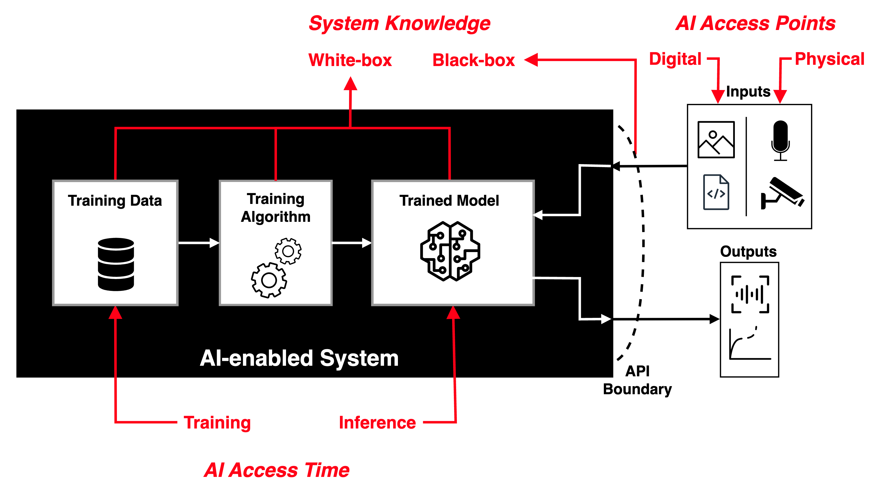
The field of adversarial machine learning (AML) is concerned with the study of attacks on machine learning (ML) algorithms and the design of robust ML algorithms to defend against these attacks [TBH+19, Sec. 1].

ML systems (and by extension AI systems) can fail in many ways, some more obvious than the others.

AML is not about ML systems failing when they make wrong inferences; it is about ML systems being tricked into making wrong inferences.

Consider three basic attack scenarios on ML systems:

Black-box evasion attack: Consider the most common deployment scenario in Fig. 1, where an ML model is deployed as an API endpoint.

  • In this black-box setting, an adversary can query the model with inputs it can control, and observe the model’s outputs, but does not know how the inputs are processed.
  • The adversary can craft adversarial data (also called adversarial examples), usually by subtly modifying legitimate test samples, that cause the model to make different inferences than what the model would have made based on the legitimate test samples — this is called an evasion attack [OV23, p. 8].
  • This technique can be used to evade a downstream task where machine learning is utilised, e.g., machine-learning-based threat detection.

White-box evasion attack: Consider the scenario in Fig. 2, where an ML model exists on a smartphone or an IoT edge node, which an adversary has access to.

  • In this white-box setting, the adversary could reverse-engineer the model.
  • With visibility into the model, the adversary can optimise its adversarial data for its evasion attack.

Poisoning attacks: Consider the scenario in Fig. 3, where an adversary has control over the training data, process and hence the model.

  • Attacks during the ML training stage are called poisoning attacks [OV23, p. 7].
  • A data poisoning attack is a poisoning attack where the adversary controls a subset of the training data by either inserting or modifying training samples [OV23, pp. 7-8].
  • A model poisoning attack is a poisoning attack where the adversary controls the model and its parameters [OV23, p. 8].
  • A backdoor poisoning attack is a poisoning attack where the adversary poisons some training samples with a trigger or backdoor pattern such that the model performs normally on legitimate test samples but abnormally on test samples containing a trigger [OV23].
Fig. 1: Black-box evasion attack: trained model is outside the adversary’s reach.
Fig. 2: White-box evasion attack: trained model is within the adversary’s reach.
Fig. 3: Poisoning attacks: trained model is poisoned with vulnerabilities.

Watch introduction to evasion attacks (informally called “perturbation attacks”) on LinkedIn Learning:

Perturbation attacks and AUPs from Security Risks in AI and Machine Learning: Categorizing Attacks and Failure Modes by Diana Kelley

Watch introduction to poisoning attacks on LinkedIn Learning:

Poisoning attacks from Security Risks in AI and Machine Learning: Categorizing Attacks and Failure Modes by Diana Kelley

In response to the threats of AML, in 2020, MITRE and Microsoft, released the Adversarial ML Threat Matrix in collaboration with Bosch, IBM, NVIDIA, Airbus, University of Toronto, etc.

Subsequently, in 2021, more organisations joined MITRE and Microsoft to release Version 2.0, and renamed the matrix to MITRE ATLAS (Adversarial Threat Landscape for Artificial-Intelligence Systems).

MITRE ATLAS is a knowledge base — modelled after MITRE ATT&CK — of adversary tactics, techniques, and case studies for ML systems based on real-world observations, demonstrations from ML red teams and security groups, and the state of the possible from academic research.

Watch MITRE’s presentation:

References

[Eid21] B. Eidson, MITRE ATLAS Takes on AI System Theft, MITRE News & Insights, June 2021. Available at https://www.mitre.org/news-insights/impact-story/mitre-atlas-takes-ai-system-theft.
[OV23] A. Oprea and A. Vassilev, Adversarial machine learning: A taxonomy and terminology of attacks and mitigations, NIST AI 100-2e2023 ipd, March 2023. https://doi.org/10.6028/NIST.AI.100-2e2023.ipd.
[Tab23] E. Tabassi, Artificial Intelligence Risk Management Framework (AI RMF 1.0), NIST AI 100-1, January 2023. https://doi.org/10.6028/NIST.AI.100-1.
[TBH+19] E. Tabassi, K. Burns, M. Hadjimichael, A. Molina-Markham, and J. Sexton, A Taxonomy and Terminology of Adversarial Machine Learning, Tech. report, 2019. https://doi.org/10.6028/NIST.IR.8269-draft.

Picture of Yee Wei Law

MITRE ATT&CK

by Yee Wei Law - Sunday, 26 March 2023, 10:57 AM
 

MITRE ATT&CK® is a knowledge base of adversary tactics (capturing “why”) and techniques (capturing “how”) based on real-world observations.

There are three versions [SAM+20]: 1️⃣ Enterprise (first published in 2015), 2️⃣ Mobile (first published in 2017), and 3️⃣ Industrial Control System (ICS, first published in 2020).

Fig. 1 below shows the fourteen MITRE ATT&CK Enterprise tactics:

Fig. 1: Tactics and top-level techniques in the MITRE ATT&CK matrix of adversary tactics and techniques. Each technique labelled with “||” branches into sub-techniques, e.g., “active scanning” consists of options “scanning IP blocks”, “vulnerability scanning” and “wordlist scanning”. See original interactive matrix.
  1. Reconnaissance (TA0043): This consists of techniques that involve adversaries actively or passively gathering information that can be used to support targeting, e.g., active scanning of IP addresses (T1595.001) and vulnerabilities (T1595.002).
  2. Resource development (TA0042): This consists of techniques that involve adversaries creating, purchasing, or compromising/stealing resources that can be used to support targeting, e.g., acquisition of domains that can be used during targeting (T1583.001).
  3. Initial access (TA0001): This consists of techniques that use various entry vectors to gain their initial foothold within a network, e.g., drive-by compromise ( T1189).
  4. Execution (TA0002): This consists of techniques that result in adversary-controlled code running on a local or remote system, e.g., abusing PowerShell commands and scripts for execution (T1059.001).
  5. Persistence (TA0003): This consists of techniques that adversaries use to maintain access to systems across restarts, changed credentials, and other interruptions that could cut off their access, e.g., adding adversary-controlled credentials to a cloud account to maintain persistent access to victim accounts and instances within the environment (T1098.001).
  6. Privilege escalation (TA0004): This consists of techniques that adversaries use to gain higher-level permissions on a system or network, e.g., abusing configurations where an application has the setuid or setgid bits set in order to get code running in a different (and possibly more privileged) user’s context (T1548.001).
  7. Defence evasion (TA0005): This consists of techniques that adversaries use to avoid detection throughout their compromise, e.g., sub-technique T1548.001.
  1. Credential access (TA0006): This consists of techniques for stealing credentials like account names and passwords, e.g., responding to LLMNR/NBT-NS network traffic to spoof an authoritative source for name resolution to force communication with an adversary-controlled system (T1557.001).
  2. Discovery (TA0007): This consists of techniques an adversary may use to gain knowledge about the system and internal network, e.g., getting a listing of local system accounts (T1087.001).
  3. Lateral movement (TA0008): This consists of techniques that adversaries use to enter and control remote systems on a network, e.g., exploiting remote services to gain unauthorised access to internal systems once inside of a network (T1210).
  4. Collection (TA0009): This consists of techniques adversaries may use to gather information and the information sources that are relevant to following through on the adversary’s objectives, e.g., sub-technique T1557.001.
  5. Command and control (TA0011): This consists of techniques that adversaries may use to communicate with systems under their control within a victim network, e.g., communicating using application-layer protocols associated with web traffic to avoid detection/network filtering by blending in with existing traffic (T1071.001).
  6. Exfiltration (TA0010): This consists of techniques that adversaries may use to steal data from your network, e.g., leverage traffic mirroring/duplication in order to automate data exfiltration over compromised network infrastructure (T1020.001).
  7. Impact (TA0040): This consists of techniques that adversaries use to disrupt availability or compromise integrity by manipulating business and operational processes, e.g., interrupting availability of system and network resources by inhibiting access to accounts utilised by legitimate users (T1531).

The Mobile tactics and ICS tactics are summarised below. Note a tactic in the Mobile context is not the same as the identically named tactic in the ICS context.

Table 1: MITRE ATT&CK Mobile tactics.
ID Name Description
TA0027 Initial Access The adversary is trying to get into your device.
TA0041 Execution The adversary is trying to run malicious code.
TA0028 Persistence The adversary is trying to maintain their foothold.
TA0029 Privilege Escalation The adversary is trying to gain higher-level permissions.
TA0030 Defense Evasion The adversary is trying to avoid being detected.
TA0031 Credential Access The adversary is trying to steal account names, passwords, or other secrets that enable access to resources.
TA0032 Discovery The adversary is trying to figure out your environment.
TA0033 Lateral Movement The adversary is trying to move through your environment.
TA0035 Collection The adversary is trying to gather data of interest to their goal.
TA0037 Command and Control The adversary is trying to communicate with compromised devices to control them.
TA0036 Exfiltration The adversary is trying to steal data.
TA0034 Impact The adversary is trying to manipulate, interrupt, or destroy your devices and data.
TA0038 Network Effects The adversary is trying to intercept or manipulate network traffic to or from a device.
TA0039 Remote Service Effects The adversary is trying to control or monitor the device using remote services.
Table 2: MITRE ATT&CK ICS tactics.
ID Name Description
TA0108 Initial Access The adversary is trying to get into your ICS environment.
TA0104 Execution The adversary is trying to run code or manipulate system functions, parameters, and data in an unauthorized way.
TA0110 Persistence The adversary is trying to maintain their foothold in your ICS environment.
TA0111 Privilege Escalation The adversary is trying to gain higher-level permissions.
TA0103 Evasion The adversary is trying to avoid security defenses.
TA0102 Discovery The adversary is locating information to assess and identify their targets in your environment.
TA0109 Lateral Movement The adversary is trying to move through your ICS environment.
TA0100 Collection The adversary is trying to gather data of interest and domain knowledge on your ICS environment to inform their goal.
TA0101 Command and Control The adversary is trying to communicate with and control compromised systems, controllers, and platforms with access to your ICS environment.
TA0107 Inhibit Response Function The adversary is trying to prevent your safety, protection, quality assurance, and operator intervention functions from responding to a failure, hazard, or unsafe state.
TA0106 Impair Process Control The adversary is trying to manipulate, disable, or damage physical control processes.
TA0105 Impact The adversary is trying to manipulate, interrupt, or destroy your ICS systems, data, and their surrounding environment.

Among the tools that support the ATT&CK framework is MITRE CALDERA™ (source code on GitHub).

  • CALDERA is a cyber security platform built on the ATT&CK framework for 1️⃣ automating adversary emulation, 2️⃣ assisting manual red-teaming, and 3️⃣ automating incident response.
  • CALDERA consists of two components:
    1. The core system: This includes an asynchronous command-and-control (C2) server with a RESTful API.
    2. Plugins: These are repositories that expand the core framework capabilities. Examples include Pathfinder, a plugin for automating ingestion of network scanning tool output.

A (blurry) demo is available on YouTube:


A complementary model to ATT&CK called PRE-ATT&CK was published in 2017 to focus on “left of exploit” behavior [SAM+20]:

  • PRE-ATT&CK documents adversarial behavior during requirements gathering, reconnaissance, and weaponisation before access to a network is obtained.
  • PRE-ATT&CK enables technology-independent modelling of an adversary’s behaviour as it attempts to gain access to an organisation or entity through the technology it leverages, spanning multiple domains (e.g., enterprise, mobile).

ATT&CK is not meant to be exhaustive, because that is the role of MITRE Common Weakness Enumeration (CWE™) and MITRE Common Attack Pattern Enumeration and Classification (CAPEC™) [SAM+20].

  • Both CWE and CAPEC are related to Common Vulnerabilities and Exposures (CVE®).
  • CVE provides a list of common identifiers for publicly known cybersecurity vulnerabilities called “CVE Records” that are assigned by CVE Numbering Authorities from around the world and are used by individuals and within products to enhance security and enable automated data exchange [MIT20].
  • Based in part on the CVE List, CWE is a community-developed list of common software and hardware security weaknesses that serves as 1️⃣ a common language, 2️⃣ a measuring stick for security tools, and as 3️⃣ a baseline for weakness identification, mitigation, and prevention efforts [MIT20].
  • Developed by leveraging CVE and CWE, CAPEC is a comprehensive dictionary and classification taxonomy of known attacks that can be used by analysts, developers, testers, and educators to advance community understanding and enhance defences.

References

[MIT20] MITRE, CVE-CWE-CAPEC Relationships, CVE page, December 2020. Available at https://cve.mitre.org/cve_cwe_capec_relationships.
[SAM+20] B. E. Strom, A. Applebaum, D. P. Miller, K. C. Nickels, A. G. Pennington, and C. B. Thomas, MITRE ATT&CK®: Design and Philosophy, MITRE Product MP180360R1, The MITRE Corporation, 2020. Available at https://www.mitre.org/sites/default/files/2021-11/prs-19-01075-28-mitre-attack-design-and-philosophy.pdf.

Picture of Yee Wei Law

MITRE CAPEC

by Yee Wei Law - Wednesday, 1 March 2023, 11:04 AM
 

MITRE’s Common Attack Pattern Enumeration and Classification (CAPEC™) effort provides a publicly available catalogue of common attack patterns to help users understand how adversaries exploit weaknesses in applications and other cyber-enabled capabilities.

Attack patterns are descriptions of the common attributes and approaches employed by adversaries to exploit known weaknesses in cyber-enabled capabilities.

  • Attack patterns define the challenges that an adversary may face and how they go about solving it.
  • They derive from the concept of design patterns applied in a destructive rather than constructive context and are generated from in-depth analysis of specific real-world exploit examples.
  • In contrast to CAPEC, MITRE ATT&CK catalogues individual techniques (more fine-grained) rather than patterns (collection of sequences of techniques).

As of writing, CAPEC stands at version 3.9 and contains 559 attack patterns.

For example, CAPEC-98 is phishing:

Definition 1: Phishing

A social engineering technique where an attacker masquerades as a legitimate entity with which the victim might interact (e.g., do business) in order to prompt the user to reveal some confidential information (typically authentication credentials) that can later be used by an attacker.

CAPEC-98 can be mapped to CWE-451 “User Interface (UI) Misrepresentation of Critical Information”.


Picture of Yee Wei Law

MITRE D3FEND

by Yee Wei Law - Tuesday, 7 March 2023, 12:54 PM
 

MITRE D3FEND is a knowledge base — more precisely a knowledge graph — of cybersecurity countermeasures/techniques, created with the primary goal of helping standardise the vocabulary used to describe defensive cybersecurity functions/technologies.

  • It serves as a catalogue of defensive cybersecurity techniques and their relationships to offensive/adversarial techniques.

The D3FEND knowledge graph was designed to map MITRE ATT&CK techniques (or sub-techniques) through digital artefacts to defensive techniques; see Fig. 1.

  • Any digital trail left by an adversary, such as Internet search, software exploit and phishing email, is a digital artefact [KS21, Sec. IVE].
Fig. 1: Mapping done by the D3FEND knowledge graph [KS21, Figs. 7-8].

Operationally speaking, the D3FEND knowledge graph allows looking up of defence techniques against specific MITRE ATT&CK techniques.

Watch an overview of the D3FEND knowledge graph from MITRE on YouTube:

References

[KS21] P. E. Kaloroumakis and M. J. Smith, Toward a knowledge graph of cybersecurity countermeasures, The MITRE Corporation, 2021. Available at https://d3fend.mitre.org/resources/D3FEND.pdf.

Picture of Yee Wei Law

MITRE Engage

by Yee Wei Law - Wednesday, 15 March 2023, 9:52 AM
 

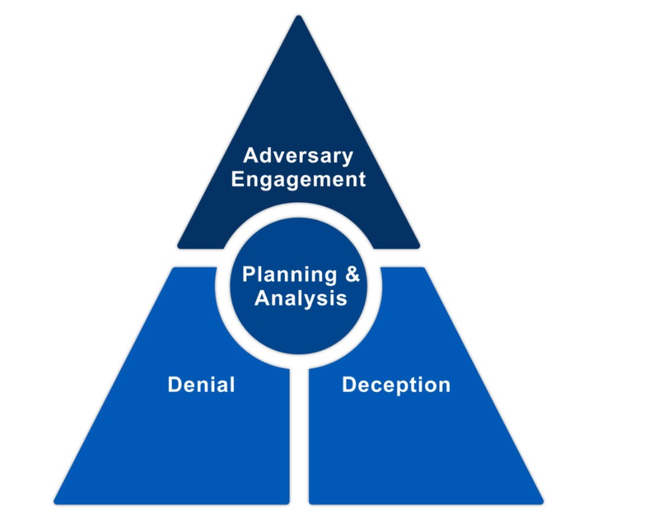
MITRE Engage (previously MITRE Shield) is a framework for planning and discussing adversary engagement operations.

  • It is meant to empower defenders to engage their adversaries and achieve their cybersecurity goals.

Cyber defense has traditionally focussed on applying defence-in-depth to deny adversaries’ access to an organisation’s critical cyber assets.

Increasingly, actively engaging adversaries proves to be more effective defence [MIT22b].

  • For example, making adversaries doubt the value of any data/information they stole drives down the value of their operations and up their operating cost.

The foundation of adversary engagement, within the context of strategic planning and analysis, is cyber denial and cyber deception [MIT22b]:

  • Cyber denial is the ability to prevent or otherwise impair adversaries’ ability to conduct their operations.
  • Cyber deception intentionally reveals deceptive facts and fictions to mislead the adversary, while concealing critical facts and fictions to prevent the adversary from making correct estimations or taking appropriate actions.

While MITRE Engage has not been around for long, the practice of cyber deception has a long history; honeypots for example can be traced back to the 1990s [Spi04, Ch. 3].

MITRE Engage prescribes the 10-Step Process, which was adapted from the process of deception in [RW13, Ch. 19], in Fig. 1:
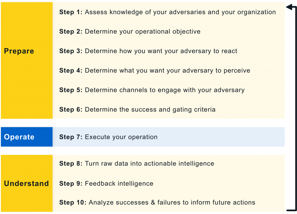
Fig. 1: The 3-phase 10-Step Process of MITRE Engage [MIT22b, p. 7].

Prepare phase:

  1. Define the operational objective, e.g., expose adversaries, or affect an adversary’s ability to operate, or elicit intelligence on an adversary’s TTPs.
  2. Construct an engagement narrative (i.e., story to deceive the adversary) that supports this objective.
  3. This narrative informs the design of the engagement environment (e.g., a network) and all operational activities.
  4. Gather all relevant stakeholders to define the acceptable level of operational risk.
  5. Construct clear Rules of Engagement (RoE) to serve as guardrails for operational activities.
  6. Put sufficient monitoring and analysis capabilities in place to ensure activities remain within set bounds.

Operate phase:

  1. Implement and deploy designed activities.
  2. Explore these activities more in the Operationalise the Methodologies section below.

Understand phase:

  1. Turn operational outputs into actionable intelligence to assess whether the operational objective is met.
  2. Capture lessons learned and refine future engagements.
Example 1: The Tularosa Study

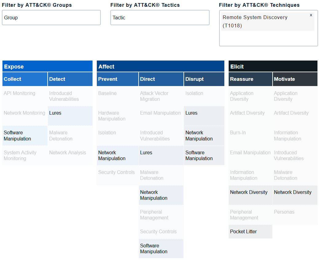
A starting point to practising cyber deception is to combine deception tools (e.g., honeypots and decoy content) with traditional defences (e.g., application programming interface monitoring, backup and recovery) [Heb22].

Contrary to intuition, cyber deception is more effective when adversaries know it is in place, because its presence exerts psychological impact on the adversaries [Heb22].

Supporting evidence is available from the 2018 Tularosa Study [FWSR+18]; watch presentation below:

Operationalise the Methodologies

The foundation of an adversary engagement strategy is the Engage Matrix:

Fig. 2: The MITRE Engage Matrix. Click on image 👆 to navigate to https://engage.mitre.org/matrix/.

The Matrix serves a shared reference that bridges the gap between defenders and decision makers when discussing and planning denial, deception, and adversary engagement activities.

The Matrix allows us to apply the theoretical 10-Step Process (see Fig. 1) to an actual operation.

The top row identifies the goals: Prepare and Understand, as well as the objectives: Expose, Affect and Elicit.

  • The Prepare and Understand Goals focus on the inputs and outputs of an operation.
  • While the Matrix is linear like the 10-Step Process, it should be viewed as cyclical.

The second row identifies the approaches, which let us make progress towards our selected goal.

The remainder of the Matrix identifies the activities.

  • The same activities often appear under one or more approach or goal/objective, e.g., Lures under ExposeDetect, AffectDirect and AffectDisrupt, because activities can be adapted to fit multiple use cases.
  • An adversary’s action may expose an unintended weakness of the adversary.
  • We can look at each MITRE ATT&CK® technique to examine the weaknesses revealed and identify engagement activities to exploit these weaknesses.
  • Fig. 3 shows an example of mapping a MITRE ATT&CK technique to an engagement activity.
Fig. 3: Mapping ATT&CK technique Remote System Discovery (T1018) to an engagement activity. Options include Software Manipulation (EAC0014), Lures (EAC0005), Network Manipulation (EAC0016), Network Diversity (EAC0007) and Pocket Litter (EAC0011).

References

[FWSR+18] K. Ferguson-Walter, T. Shade, A. Rogers, M. Trumbo, K. Nauer, K. Divis, A. Jones, A. Combs, and R. Abbott, The Tularosa Study: An Experimental Design and Implementation to Quantify the Effectiveness of Cyber Deception, Tech. Report SAND2018-5870C, Sandia National Lab, 2018. Available at https://www.osti.gov/servlets/purl/1524844.
[Heb22] C. Hebert, Trust Me, I’m a Liar, IEEE Security & Privacy 20 no. 6 (2022), 79–82. https://doi.org/10.1109/MSEC.2022.3202625.
[MIT22b] MITRE Engage, A Starter Kit in Adversary Engagement, 2022, version 1.0. Available at https://engage.mitre.org/wp-content/uploads/2022/04/StarterKit-v1.0-1.pdf.
[RW13] H. Rothstein and B. Whaley, Art and Science of Military Deception, Artech House, 2013. Available at https://app.knovel.com/hotlink/toc/id:kpASMD0003/art-science-military/art-science-military.
[Spi04] L. Spitzner, Honeypots: Tracking Hackers, Addison-Wesley Professional, 2004. Available at https://learning.oreilly.com/library/view/honeypots-tracking-hackers/0321108957/.

Picture of Yee Wei Law

Model checking

by Yee Wei Law - Sunday, 14 May 2023, 5:01 PM
 

Model checking is a method for formally verifying that a model satisfies a specified property [vJ11, p. 1255].

Model checking algorithms typically entail enumerating the program state space to determine if the desired properties hold.

Example 1 [CDW04]

Developed by UC Berkeley, MOdelchecking Programs for Security properties (MOPS) is a static (compile-time) analysis tool, which given a program and a security property (expressed as a finite-state automaton), checks whether the program can violate the security property.

The security properties that MOPS checks are temporal safety properties, i.e., properties requiring that programs perform certain security-relevant operations in certain orders.

An example of a temporal security property is whether a setuid-root program drops root privileges before executing an untrusted program; see Fig. 1.

Fig. 1: An example of a finite-state automaton specifying a temporal security property [CDW04, Figure 1(a)]

References

[CDW04] H. Chen, D. Dean, and D. Wagner, Model Checking One Million Lines of C Code, in NDSS, 2004.
[vJ11] H. C. van Tilborg and S. Jajodia (eds.), Encyclopedia of Cryptography and Security, Springer, Boston, MA, 2011. https://doi.org/10.1007/978-1-4419-5906-5.

N

Picture of Yee Wei Law

NIST Cybersecurity Framework

by Yee Wei Law - Wednesday, 8 March 2023, 10:52 AM
 

The National Institute of Standards and Technology (NIST) has an essential role in identifying and developing cybersecurity risk frameworks for voluntary use by owners and operators of critical infrastructure (see Definition 1) [NIS18, Executive Summary].

Definition 1: Critical infrastructure [NIS18, Sec. 1.0]

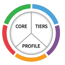
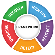
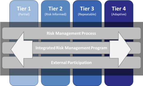
Systems and assets, whether physical or virtual, so vital that the incapacity or destruction of such systems and assets would have a debilitating impact on security, national economic security, national public health or safety, or any combination of those matters.

One such framework is the Framework for Improving Critical Infrastructure Cybersecurity (Cybersecurity Framework for short), for which NIST is maintaining an official website.

As of writing, the latest version of the NIST Cybersecurity Framework is 1.1 [NIS18].

The Cybersecurity Framework provides a common language for understanding, managing and expressing cybersecurity risks to internal and external stakeholders [NIS18, Sec. 2.0].

The Cybersecurity Framework has three parts: 1️⃣ Framework Core, 2️⃣ Implementation Tiers, and 3️⃣ Framework Profiles.

Framework Core

This is a set of cybersecurity activities, desired outcomes and applicable references (industry standards, guidelines and practices) that are common across critical infrastructure sectors [NIS18, Sec. 1.1].

The Framework Core consists of five concurrent and continuous Functions that provide a high-level strategic view of the lifecycle of an organisation’s management of cybersecurity risks:

  1. Identify: Develop an organisational understanding to manage cybersecurity risks to systems, people, assets, data and capabilities [NIS18, p. 7].

    Applicable activities include [MMQT21]:

    • identifying critical enterprise processes and assets;
    • documenting information flows (how information is collected, stored, updated and used);
    • maintaining hardware and software inventories;
    • establishing cybersecurity policies specifying roles, responsibilities and procedures in integration with enterprise risk considerations;
    • identifying and assessing vulnerabilities and threats;
    • identifying, prioritising, executing and tracking risk responses.
  2. Protect: Develop and implement appropriate safeguards to ensure delivery of critical services [NIS18, p. 7].

    Applicable activities include [MMQT21]:

    • managing access to assets and information;
    • safeguarding sensitive data, including applying authenticated encryption and deleting data that are no longer needed;
    • making regular backups and storing backups offline;
    • deploying firewalls and other security products, with configuration management, to protect devices;
    • keeping device firmware and software updated, while regularly scanning for vulnerabilities;
    • training and regularly retraining users to maintain cybersecurity hygiene.
  3. Detect: Develop and implement appropriate activities to identify the occurrence of a cybersecurity event [NIS18, p. 7].

    Applicable activities include [MMQT21]:

    • developing, testing and updating processes and procedures for detecting unauthorised entities and actions in the cyber and physical environments;
    • maintaining logs and monitoring them for anomalies, including unexpected changes to systems or accounts, illegitimate communication channels and data flows.
  4. Respond: Develop and implement appropriate activities to take action regarding a detected cybersecurity incident [NIS18, p. 8].

    Applicable activities include [MMQT21]:

    • making, testing and updating response plans, including legal reporting requirements, to ensure each personnel is aware of their responsibilities;
    • coordinating response plans and updates with all key internal and external stakeholders.
  5. Recover: Develop and implement appropriate activities to maintain plans for resilience and to restore any capabilities or services that were impaired by a cybersecurity incident [NIS18, p. 8].

    Applicable activities include [MMQT21]:

    • making, testing and updating recovery plans;
    • coordinating recovery plans and updates with all key internal and external stakeholders, paying attention to what, how and when information is shared;
    • managing public relations and company reputation.

Each Function comprises Categories, and each Category comprises Subcategories, and for each Subcategory, Informative References are provided [NIS18, Sec. 2.1].

  • A Category is a cybersecurity outcome closely tied to programmatic needs and particular activities.
  • A Subcategory is an outcome of technical and/or management activities for supporting achievement of the outcomes in each Category.
  • An Informative Reference is a specific part of a standard, guideline and practice common among critical infrastructure sectors that illustrates a method to achieve the outcomes associated with each Subcategory.

Fig. 1 shows Categories, and the Subcategories under the Category “Business Environment”, and furthermore the Informative References for each of these Subcategories.

Fig. 1: Functions, Categories, sample Subcategories and sample Informative References. Details about these Informative References can be found in [NIS18, p. 44].
Implementation Tiers

The four tiers in Table 1 provide context on how an organisation views cybersecurity risks and the processes in place to manage those risks [NIS18, p. 8].

Table 1: Implementation tiers [NIS18, pp. 9-11].
Tier Risk management process Integrated risk management program External participation
1, Partial Not formalised, ad hoc and reactive.

Limited cybersecurity awareness.

Risk management is irregular and case-by-case.

Organisation does not engage with other entities, and lacks awareness of cyber supply chain risks.
2, Risk-informed

Formalised but not organisation-wide.

Prioritisation of cybersecurity objectives and activities is directly informed by organisational risks, business requirements, or the threat environment.

Cybersecurity awareness exists at the organisational level, but risk management is not organisation-wide.

Irregular risk assessment of assets.

Organisation receives information from other entities and generates some of its own, but may not share information with others.

Organisation is aware of cyber supply chain risks, but does not respond formally to the risks.

3, Repeatable Formalised and regularly updated based on the application of risk management processes to changes in business requirements and the threat landscape.

Risk management is organisation-wide.

Organisation accurately and consistently monitors cybersecurity risks of assets.

Organisation responds effectively and consistently to changes in risks.

Cybersecurity is considered through all lines of operation.

Organisation receives information from other entities and share its original information with others.

Organisation is aware of cyber supply chain risks, and usually responds formally to the risks.

4, Adaptive

Formalised and adaptable to experience and forecast.

Continuously improved leveraging advanced cybersecurity technologies and practices, to respond to evolving, sophisticated threats in a timely and effective manner.

Risk management is organisation-wide.

Decision making is grounded in clear understanding of the relationship between cybersecurity risks and financial risks / organisational objectives.

Risk management is integral to organisational culture and is supported by continuous awareness of activities on systems and networks.

Organisation receives, generates and reviews prioritised information to inform continuous risk assessment.

Organisation uses real-time information to respond formally and consistently to cyber supply chain risks.

Implementation tiers do not represent maturity levels; they are meant to support organisational decision making about how to manage cybersecurity risks.

Framework Profiles

A Framework Profile (“Profile”) is a representation of the outcomes that a particular system or organisation has selected from the Framework Categories and Subcategories [NIS18, Appendix B].

A Profile specifies the alignment of the Functions, Categories, and Subcategories with the business requirements, risk tolerance, and resources of an organisation [NIS18, Sec. 2.3].

A Profile enables organisations to establish a roadmap for reducing cybersecurity risks, that 1️⃣ is well aligned with organisational and sector goals, 2️⃣ considers legal/regulatory requirements and industry best practices, and 3️⃣ reflects risk management priorities [NIS18, Sec. 2.3].

For example,

  • The NIST Interagency Report 8401 [LSB22] specifies a Profile for securing satellite ground segments.
  • A Profile for securing hybrid satellite networks is currently under development.
  • More examples of Profiles can be found here.

Watch a more detailed explanation of the Cybersecurity Framework presented at RSA Conference 2018:

References

[LSB22] S. Lightman, T. Suloway, and J. Brule, Satellite ground segment: Applying the cybersecurity framework to satellite command and control, NIST IR 8401, December 2022. https://doi.org/10.6028/NIST.IR.8401.
[MMQT21] A. Mahn, J. Marron, S. Quinn, and D. Topper, Getting Started with the NIST Cybersecurity Framework: A Quick Start Guide, NIST Special Publication 1271, August 2021. https://doi.org/10.6028/NIST.SP.1271.
[MMBM22] J. McCarthy, D. Mamula, J. Brule, and K. Meldorf, Cybersecurity Framework Profile for Hybrid Satellite Networks (HSN): Final Annotated Outline, NIST Cybersecurity White Paper, NIST CSWP 27, November 2022. https://doi.org/10.6028/NIST.CSWP.27.
[NIS18] NIST, Framework for Improving Critical Infrastructure Cybersecurity, Version 1.1, April 2018. Available at https://www.nist.gov/cyberframework/framework.

O

Picture of Yee Wei Law

Open Systems Interconnection (OSI)

by Yee Wei Law - Monday, 22 May 2023, 12:18 AM
 

Imagine writing a piece of networking software.

  • It needs to enable two neighbouring (i.e., directly connected) devices to communicate.
  • It also needs to enable two devices separated by multiple hops to communicate.

The Open Systems Interconnection (sometimes Open Systems Interconnect or simply OSI) model 1️⃣ enables networking software to be built in a structured manner; 2️⃣ provides an interoperability framework for networking protocols.

History: The OSI model was introduced in 1983 by several major computer and telecom companies; and was adopted by ISO as an international standard in 1984 [Imp22].

  • The second and latest edition of the international standard is ISO/IEC 7498-1:1994 [ISO94].

Watch the following video for a quick overview:

Learning the seven layers from Networking Foundations: Networking Basics by Kevin Wallace

More details follows.

The OSI model is a logical (as opposed to physical) model that consists of seven nonoverlapping layers (going bottom-up, opposite to Fig. 1):

  1. Layer 1 (L1), physical layer [TW11, p. 43]: This layer transmits and/or receives raw bits (see Fig. 2) over a communication channel (e.g., coaxial cable, optical fibre, RF channel).

    This layer deals with mechanical, electrical, and timing interfaces, as well as the physical transmission medium, which lies below the physical layer.

    For example, the IEEE Standard for Ethernet [IEE22] specifies several variants of the physical layer and one data link layer.

  2. Layer 2 (L2), data link layer [TW11, p. 43]: This layer transforms a raw transmission facility into a line that appears free of undetected transmission errors, by masking the real errors so the network layer above does not see them.

    Input data is encapsulated in data frames (see Fig. 2) which are transmitted sequentially.

    For example, the Challenge-Handshake Authentication Protocol (CHAP, see RFC 1994 and RFC 2433) is a link-layer protocol.

Fig. 1: The OSI model in a nutshell [Clo22].
Fig. 2: The OSI model and associated terms [TW11, Figure 1-20]. While the bottom three layers are peer-to-peer, the upper layers are end-to-end.
  1. Layer 3 (L3), network layer [TW11, pp. 43-44]: This layer controls the operation of a subnet (see Fig. 2), by determining how packets (see Fig. 2) are routed from a source to a destination.

    For example, the Internet Protocol Security (IPsec) is a network-layer protocol.

  2. Layer 4 (L4), transport layer [TW11, pp. 44]: This layer accepts data from above it, split it up into smaller units, called transport protocol data units (TPDUs, see Fig. 2), if need be, passes these to the network layer, and ensures that all pieces arrive correctly and efficiently at the other end.

    For example, the Transmission Control Protocol (TCP) and User Datagram Protocol (UDP) are transport-layer protocols (see Fig. 1).

  1. Layer 5 (L5), session layer [TW11, pp. 44-45]: This layer enables users on different machines to establish sessions between them.

    Sessions offer various services, including dialog control (keeping track of whose turn it is to transmit), token management (preventing two parties from attempting the same critical operation simultaneously), and synchronisation (checkpointing long transmissions to allow them to pick up from where they left off in the event of a crash and subsequent recovery).

    For example, SOCKS5 (see RFC 1928) is a session-layer protocol.

  2. Layer 6 (L6), presentation layer [TW11, p. 45]: This layer manages the syntax and semantics of the information to be transmitted.

    For most protocols however, the distinction between the presentation layer and application layer is blur. For example, the HyperText Transfer Protocol (HTTP) is commonly classified as an application-layer protocol although it has clear presentation-layer functions such as encoding, decoding, and managing different content types [FNR22].

  3. Layer 7 (L7), application layer [TW11, p. 45]: This layer implements a suite of protocols for supporting end-user applications.

    For example, HTTP is a stateless application-layer protocol for distributed, collaborative, hypertext information systems [FNR22]. HTTP supports eight “methods”, including the GET method for requesting transfer of a target resource in a specified representation [FNR22, Sec. 9.3.1].

The OSI model is not the only networking model. The TCP/IP reference model plays an equally important role in the history of networking.

The APRANET and its descendent — the Internet as we know it — are based on the TCP/IP model.

The TCP/IP model has only four layers, as shown in Fig. 3.

Fig. 3 also shows the different protocols occupying the different layers of the TCP/IP model.

Both models use 1️⃣ the transport and lower layers to provide an end-to-end, network-independent transport service; and 2️⃣ the layers above transport for applications leveraging the transport service.

Most real-world protocol stacks are developed based on a hybrid of the OSI and TCP/IP models, consisting of these layers (from bottom to top): physical, data link, network, transport, application [TW11, Sec. 1.4.3].

Fig. 3: Comparing the OSI model and TCP/IP model [Imp22].

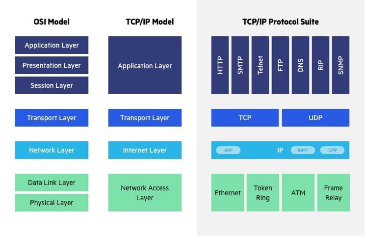
The salient differences between the OSI and TCP/IP models are summarised in Table 1 below.

Table 1: Salient differences between the OSI and TCP/IP models [TW11, Secs. 1.4.2-1.4.5].
OSI model TCP/IP model
Created before the protocols residing in the different layers were. Created after the protocols were.
The OSI model differentiates services (provided by each layer), interfaces (between adjacent layers) and protocols (implementing different layers) from each other. This abstraction is consistent with object-oriented programming. The TCP/IP model appears to be more monolithic, and this provides little help with engineering a non-TCP/IP stack.
The data link layer originally only catered for point-to-point communications. For broadcast networks, a medium access control sublayer had to be grafted onto the OSI model. No sublayering is needed within the network access layer.
Too many layers, because the top three layers can often be collapsed into a single application layer in practical implementations. Not enough layers, because the network access layer should really be split into two layers: physical and data link. For example, IEEE 802.3 (Ethernet) and IEEE 802.11 (Wi-Fi) protocols have distinct specifications for the physical and data link layers.
The OSI model supports both connectionless and connection-oriented communication in the network layer, but only connection-oriented communication in the transport layer. The TCP/IP model supports only connectionless communication in the network layer, but both connectionless and connection-oriented communication in the transport layer. Having these two choices in the transport layer is good for simple request-response protocols.

References

[CCI91] CCITT, ITU, Security architecture for Open Systems Interconnection for CCITT applications, Recommendation X.800 (03/91), 1991. Available at https://www.itu.int/rec/T-REC-X.800-199103-I/en.
[Clo22] Cloudfare, What is the OSI Model?, DDoS Glossary, 2022, accessed 28 Nov 2022. Available at https://www.cloudflare.com/learning/ddos/glossary/open-systems-interconnection-model-osi/.
[FNR22] R. Fielding, M. Nottingham, and J. Reschke, HTTP Semantics, IETF RFC 9110, June 2022.
[IEE22] IEEE, IEEE Standard for Ethernet, IEEE Std 802.3-2022 (Revision of IEEE Std 802.3-2018), 2022. https://doi.org/10.1109/IEEESTD.2022.9844436.
[Imp22] Imperva, OSI Model, Learning Center, 2022, accessed 1 Dec 2022. Available at https://www.imperva.com/learn/application-security/osi-model/.
[ISO94] ISO/IEC, Information technology – open systems interconnection – basic reference model: The basic model, International Standard ISO/IEC 7498-1:1994 second edition, November 1994, corrected and reprinted 1996-06-15. Available at https://www.iso.org/standard/20269.html.
[TW11] A. S. Tanenbaum and D. J. Wetherall, Computer Networks, 5th ed., Prentice Hall, 2011.

P

Picture of Yee Wei Law

Physical-layer security

by Yee Wei Law - Wednesday, 17 May 2023, 12:00 AM
 

References

[LFZZ20] B. Li, Z. Fei, C. Zhou, and Y. Zhang, Physical-layer security in space information networks: A survey, IEEE Internet of Things Journal 7 no. 1 (2020), 33–52. https://doi.org/10.1109/JIOT.2019.2943900.

Picture of Yee Wei Law

Physical unclonable function (PUF)

by Yee Wei Law - Wednesday, 5 April 2023, 9:08 AM
 

Physical unclonable functions (PUFs, see Definition 1) serve as a physical and unclonable alternative to digital cryptographic keys.

Definition 1: Physical unclonable function (PUF) [GASA20]

A device that exploits inherent randomness introduced during manufacturing to give a physical entity a unique “fingerprint” or trust anchor.

Think of a PUF as a keyed hash function, where the key is built-in and unique due to manufacturing variations [GASA20].

  • Given an input, which we shall call a challenge, a PUF outputs a response. The challenge-response pair (CRP) is unique to the PUF.
  • Every CRP is used only once.

Types of PUFs include 1️⃣ optical PUFs, 2️⃣ arbiter PUFs, 3️⃣ memory-based intrinsic PUFs [GASA20].

  • An intrinsic PUF is a PUF that is already embedded within a device at the time of manufacturing.
  • The first intrinsic PUF was introduced in 2007 in the form of an SRAM PUF.
  • Flash memory PUFs and DRAM PUFs were subsequently introduced.
  • A memory-based PUF usually offers desired independence among response bits, so its primary application is on-demand derivation of volatile cryptographic keys.

Watch a high-level introduction to SRAM PUF:

References

[GASA20] Y. Gao, S. F. Al-Sarawi, and D. Abbott, Physical unclonable functions, Nat Electron 3 (2020), 81–91. https://doi.org/10.1038/s41928-020-0372-5.

Picture of Yee Wei Law

Proximity-1 Space Link Protocol

by Yee Wei Law - Sunday, 10 March 2024, 7:37 PM
 

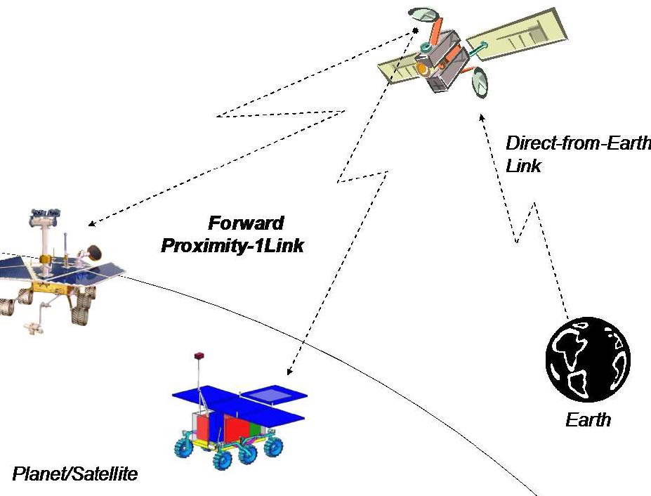
Proximity-1 covers the data link layer [CCS20d] and physical layer [CCS13b].

Proximity-1 enables communications among probes, landers, rovers, orbiting constellations, and orbiting relays in a proximate environment, up to about 100,000 km [CCS13c].

These scenarios are devoid of manual intervention from ground operators, and furthermore, resources such as computational power and storage are typically limited at both ends of the link.

In fact, Proximity-1 has been field-tested in the 2004-2005 Mars missions; see Figs. 1-2 for illustration.

Fig. 1: Proximity-1 relay link for telecommands [CCS13c, Figure 2-1a].
Fig. 2: Proximity-1 relay link for telemetry [CCS13c, Figure 2-1b].

In contrast, the AOS/TC/TM Space Data Link Protocols are meant for Earth-deep space links, over extremely long distances.

Proximity-1 supports symbol rates of up to 4,096,000 coded symbols per second.

Designed for the Mars environment, the physical Layer of Proximity-1 only uses UHF frequencies [CCS13b, Sec. 1.2].

The frequency range consists of 60 MHz between 390 MHz to 450 MHz with a 30 MHz guard-band between forward and return frequency bands, specifically 435-450 MHz for the forward channel and 390-405 MHz for the return channel [CCS13b, Sec. 3.3.2].

References

[CCS13b] CCSDS, Proximity-1 Space Link Protocol—Physical Layer, Recommended Standard CCSDS 211.1-B-4, The Consultative Committee for Space Data Systems, December 2013. Available at https://public.ccsds.org/Pubs/211x1b4e1.pdf.
[CCS13c] CCSDS, Proximity-1 Space Link Protocol—Rationale, Architecture, and Scenarios, Recommended Standard CCSDS 210.0-G-2, The Consultative Committee for Space Data Systems, December 2013. Available at https://public.ccsds.org/Pubs/210x0g2e1.pdf.
[CCS20d] CCSDS, Proximity-1 Space Link Protocol—Data Link Layer, Recommended Standard CCSDS 211.0-B-6, The Consultative Committee for Space Data Systems, July 2020. Available at https://public.ccsds.org/Pubs/211x0b6.pdf.

Picture of Yee Wei Law

Public-key cryptography

by Yee Wei Law - Wednesday, 31 May 2023, 1:11 PM
 

Also known as asymmetric-key cryptography, public-key cryptography (PKC) uses a pair of keys called a public key and a private key for 1️⃣ encryption and decryption, as well as 2️⃣ signing and verification.

Encryption and decryption

For 👩 Alice to send a confidential message to 🧔 Bob,

  • 👩 Alice uses 🧔 Bob’s public key to encrypt her secret plaintext and sends the ciphertext to Bob.
  • 🧔 Bob uses his private key to decrypt the ciphertext.
  • 👩 Alice’s keys are not involved unless someone wants to send confidential messages to Alice.

However,

  • PKC is not usually used for encryption because of the computational cost and the ciphertext length.
  • The more powerful quantum computers become, the longer the keys need to be, the higher the computational costs and the longer the ciphertexts become.
  • Instead, a key establishment protocol is used to establish a symmetric key between two parties and the symmetric key is used for encryption instead.

Signing and verification

For 👩 Alice to assure 🧔 Bob a message really originated from her (i.e., for Bob to authenticate her message),

  • 👩 Alice signs the message with her private key and sends the signed message to 🧔 Bob.
  • 🧔 Bob uses Alice’s public key to verify the signature attached to the message.
  • Successful verification assures 🧔 Bob that the message was signed by 👩 Alice.
  • Simultaneously, 👩 Alice cannot repudiate (see Definition 1) the fact that she signed the message.
Definition 1: Non-repudiation [NIS13]

A service that is used to provide assurance of the integrity and origin of data in such a way that the integrity and origin can be verified and validated by a third party as having originated from a specific entity in possession of the private key (i.e., the signatory).

The ability of PKC to generate and verify signatures gives rise to 📜 digital certificates, an essential feature of PKC.

Digital certificates and public-key infrastructure (PKI)

Suppose 👩 Alice is somebody everybody trusts.

  • When 👩 Alice signs 🧔 Bob’s public key, anybody can verify Bob’s public key using Alice’s public key.
  • Successful verification means we can trust that the public key is Bob’s because we trust Alice.
  • Essentially, 🧔 Bob’s public key with 👩 Alice’s signature on it serves a 📜 digital certificate (see Definition 2) certifying Bob’s identity.
Definition 3: Digital certificate [ENISA]

Also called a public-key certificate, a digital certificate is an electronic data structure that binds an entity (e.g., an institution, a person, a computer program, a web address) to its public key.

Watch a quick introduction to digital certificates on LinkedIn Learning:

Digital certificates and signing from Ethical Hacking: Cryptography by Stephanie Domas

Digital certificates are only useful if we can trust their signatories.

To ensure signatories and hence certificates can be trusted, PKC relies on a public-key infrastructure (PKI, see Definition 3) to work.

Definition 3: Public-key infrastructure (PKI)

In ENISA’s certificate-centric definition, a PKI is a combination of policies, procedures and technology needed to manage digital certificates in a PKC scheme.

In ITU-T’s [ITU19] key-centric definition, a PKI is an infrastructure able to support the management of public keys able to support authentication, encryption, integrity and non-repudiation services.

Watch a quick introduction to PKI from an operational viewpoint on LinkedIn Learning:

Cryptography: Public key infrastructure and certificates from CISA Cert Prep: 5 Information Asset Protection for IS Auditors by Human Element LLC and Michael Lester

A PKI, as specified in the ITU-T X.509 [ITU19] standard, consist of certification authorities (CAs).

  • One or more CAs are trusted to create and digitally sign public-key certificates in response to certificate signing requests (CSRs).

  • A CA may optionally create the subjects’ keys.
  • A CA certificate is a public-key certificate for one CA [ITU19, Sec. 7.4]

    • issued by another CA, in which case the CA certificate is a cross-certificate;
    • issued by the same CA, in which case the CA certificate is a self-issued certificate.

      If the signing key is the private key associated with the public key signed, the self-issued certificate is a self-signed certificate.

  • Thus, CAs can clearly exist in a hierarchy, e.g., the two-tier hierarchy in Fig. 1, or the three-tier hierarchy in Fig. 2.
  • In a hierarchy, the root CA serves as the trust anchor [ITU19, Sec. 7.5].
  • Examples of CAs: IdenTrust, DigiCert Group, others.
  • An example of a software solution that implements CA functionality is Cloudfare’s CFSSL.

Fig. 1: A two-tier hierarchy of CAs [NCS20, p. 6].

In a 2-tier hierarchy, a root CA issues certificates to intermediate CAs, and intermediate CAs issue certificates to end entities.

Intermediate CAs are often organised to issue certificates for certain functions, e.g., a technology use case, VPN, web application.

Alternatively, the CAs can be organised by organisational function, e.g., user / machine / service authentication.

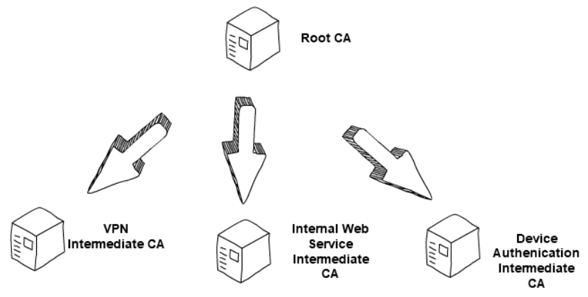
Fig. 2: A three-tier hierarchy of CAs [NCS20, p. 6].

In a 3-tier hierarchy, there is a root CA and two levels of intermediate CAs, in which the lowest layer issues certificates to end entities.

This setup is often used to give an extra layer of separation between the root CA and the intermediate issuing certificates to end entities.

The number of tiers in a CA hierarchy is a balance between the level of separation required and the tolerable administration overheard.

A PKI also has registration authorities (RAs).

  • One or more RAs are responsible for those aspects of a CA’s responsibilities that are related to identification and authentication of the subject of a public-key certificate to be issued by that CA.
  • An RA may either be a separate entity or be an integrated part of the CA.
  • CAs typically play the role of RA as well.
  • An example of a software solution that implements RA functionality is PrimeKey’s EJBCA Registration Authority.

Although the X.509 standard does not specify any validation authority (VA), a VA allows an entity to check that a certificate has not been revoked [NCS20, p. 3].

  • The VA role is often carried out by an online facility hosted by an organisation who operates the PKI.
  • VAs often use the Online Certificate Status Protocol (OCSP, see RFC 6960) or certificate revocation lists (CRLs) to advertise revoked certificates.
  • Fig. 3 illustrates the interactions among an RA, a CA and a VA in a PKI.
  • An example of a software solution that implements VA functionality is PrimeKey’s EJBCA Validation Authority.
Fig. 3: The human representing an organisation registers their public key with an RA, which gets a CA to generate a digital certificate certifying the organisation’s key. The digital certificate enables website users to verify the organisation’s website. For the verification, a user can use a VA. Image from Wikipedia.

Public-key cryptosystems

Algorithmically speaking, there is more than one way of constructing a public-key cryptosystem.

Standard public-key cryptosystems: 1️⃣ Rivest-Shamir-Adleman (RSA) cryptosystem, 2️⃣ elliptic-curve cryptosystems.

These cryptosystems rely on the hardness of certain computational problems for their security.

The hardness of these computational problems has come under threat of quantum computers and quantum algorithms like Shor’s algorithm.

As a countermeasure, NIST has been searching for post-quantum cryptography (PQC, also called quantum-resistant cryptography).

As of writing, there are three PQC candidates.

References

[ITU19] ITU-T, Information technology – Open Systems Interconnection – The Directory: Public-key and attribute certificate frameworks, Recommendation ITU-T X.509 | ISO/IEC 9594-8, October 2019. Available at https://www.itu.int/rec/T-REC-X.509-201910-I/en.
[NCS20] NCSC, Design and build a privately hosted Public Key Infrastructure: Principles for the design and build of in-house Public Key Infrastructure (PKI), National Cyber Security Centre guidance, November 2020. Available at https://www.ncsc.gov.uk/collection/in-house-public-key-infrastructure/introduction-to-public-key-infrastructure/ca-hierarchy.
[NIS13] NIST, Digital Signature Standard (DSS), FIPS PUB 186-4, Information Technology Laboratory, National Institute of Standards and Technology, 2013. https://doi.org/10.6028/NIST.FIPS.186-4.
[SC16] J. J. Stapleton and W. Clay Epstein, Security without Obscurity: A Guide to PKI Operations, CRC Press, 2016. https://doi.org/10.1201/b19725.

R

Picture of Yee Wei Law

Rivest-Shamir-Adleman (RSA) cryptosystem

by Yee Wei Law - Saturday, 19 August 2023, 8:11 PM
 

See 👇 attachment (coming soon) or the latest source on Overleaf.

Tags:

Picture of Yee Wei Law

Rowhammer

by Yee Wei Law - Saturday, 22 April 2023, 11:00 PM
 

Not ready for 2023 but see reference below.

References

[SD15] M. Seaborn and T. Dullien, Exploiting the DRAM rowhammer bug to gain kernel privileges, Black Hat, 2015. Available at https://www.blackhat.com/docs/us-15/materials/us-15-Seaborn-Exploiting-The-DRAM-Rowhammer-Bug-To-Gain-Kernel-Privileges.pdf.

S

Picture of Yee Wei Law

Safe programming languages

by Yee Wei Law - Friday, 12 May 2023, 3:18 PM
 

A safe programming language is one that is memory-safe (see Definition 1), type-safe (see Definition 2) and thread-safe (see Definition 3).

Definition 1: Memory safety [WWK+21]

Assurance that adversaries cannot read or write to memory locations other than those intended by the programmer.

A significant percentage of software vulnerabilities have been attributed to memory safety issues [NSA22], hence memory safety is of critical importance.

Examples of violations of memory safety can be found in the discussion of common weakness CWE-787 and CWE-125.

Definition 2: Type safety [Fru07, Sec. 1.1]

Type safety is a formal guarantee that the execution of any program is free of type errors, which are undesirable program behaviours resulting from attempts to perform on some value an operation that is inappropriate to the type of the value.

For example, applying a factorial function to any value that is not an integer should result in a type error.

Type safety ⇒ memory safety, but the converse is not true [SM07, Sec. 6.5.2], hence type safety is commonly considered to be a central theme in language-based security [Fru07].

Type-safe programming languages, e.g., Java , Ruby, C#, Go, Kotlin, Swift and Rust, have been around for a while. However, memory-unsafe languages are still being used because:

  • Type-safety features come at the expense of performance. There is for example overhead associated with checking the bounds on every array access [NSA22].

    Even the current speed champion, Rust, among the type-safe languages, and the only type-safe language that has made it to the Linux kernel [VN22] and Windows kernel [Thu23], is not efficient enough for all use cases [Iva22]. This is one of the reasons why Google is still trying to create a successor to C++ called Carbon.

  • Type-safety features also come at the expense of resource requirements. Most memory-safe languages use garbage collection for memory management [NSA22], and this translates to higher memory usage.
  • Although most type-safe languages are supported on the mainstream computing platforms (e.g., Wintel), the same cannot be said of embedded platforms.

    It can be challenging to program a resource-constrained platform using a type-safe language.

  • There is already a vast amount of legacy code in C/C++ and other memory-unsafe languages.

    The cost to port legacy code, including the cost of training programmers, is often prohibitive.

    Depending on the language, interfacing memory-safe code with unsafe legacy code can be cumbersome.

  • Besides invoking unsafe code, it is all too easy to do unsafe things with a type-safe language, e.g., not checking user input, not implementing access control.

    Programmers often use this as an excuse to not use a different language than what they are familiar with.

Nevertheless, adoption of type-safe languages, especially Rust, has been on the rise [Cla23].

Thread safety rounds up the desirable properties of type-safe languages.

Definition 3: Thread safety [Ora19, Ch. 7]

The avoidance of data races, which occur when data are set to either correct or incorrect values, depending upon the order in which multiple threads access and modify the data.

Watch the following LinkedIn Learning video about thread safety:

Thread safety from IoT Foundations: Operating Systems Fundamentals by Ryan Hu

Rust is an example of a type-safe language that is also thread-safe.

References

[Cla23] T. Claburn, Memory safety is the new black, fashionable and fit for any occasion: Calls to avoid C/C++ and embrace Rust grow louder, The Register, January 2023. Available at https://www.theregister.com/2023/01/26/memory_safety_mainstream/.
[Fru07] N. G. Fruja, Type safety of C# and .Net CLR, Ph.D. thesis, ETH Zürich, 2007. https://doi.org/10.3929/ethz-a-005357653.
[Iva22] N. Ivanov, Is Rust C++-fast? Benchmarking System Languages on Everyday Routines, arXiv preprint arXiv:2209.09127, 2022. https://doi.org/10.48550/ARXIV.2209.09127.
[NSA22] NSA, Software memory safety, Cybersecurity Information Sheet, November 2022. Available at https://media.defense.gov/2022/Nov/10/2003112742/-1/-1/0/CSI_SOFTWARE_MEMORY_SAFETY.PDF.
[Ora19] Oracle, Multithreaded programming guide, Part No: E54803, March 2019. Available at https://docs.oracle.com/cd/E53394_01/pdf/E54803.pdf.
[SM07] S. Smith and J. Marchesini, The Craft of System Security, Addison-Wesley Professional, 2007. Available at https://learning.oreilly.com/library/view/the-craft-of/9780321434838/.
[Thu23] P. Thurrott, First Rust Code Shows Up in the Windows 11 Kernel, blog post, May 2023. Available at https://www.thurrott.com/windows/windows-11/282995/first-rust-code-shows-up-in-the-windows-11-kernel.
[VN22] S. Vaughan-Nichols, Linus Torvalds: Rust will go into Linux 6.1, ZDNET, September 2022. Available at https://www.zdnet.com/article/linus-torvalds-rust-will-go-into-linux-6-1/.
[WWK+21] D. Wagner, N. Weaver, P. Kao, F. Shakir, A. Law, and N. Ngai, Computer security, online textbook for CS 161 Computer Security at UC Berkeley, 2021. Available at https://textbook.cs161.org/.

Picture of Yee Wei Law

Satellite frequency bands

by Yee Wei Law - Tuesday, 18 July 2023, 11:49 PM
 

Fig. 1 depicts the usage of different frequency bands.

Fig. 1: SATCOM frequency bands [McC09, slide 41], where VHF = very high frequency, UHF = ultra high frequency, SHF = super high frequency, EHF = extra high frequency.

IEEE Standard 512 [IEE20] defines the letters designating the frequency bands.

According to ESA, the main satellite frequency bands range from L to Ka; see also the same link for discussion of different usage of the frequency bands.

References

[McC09] D. McClure, Overview of satellite communications, slides, 2009. Available at https://olli.gmu.edu/docstore/800docs/0909-803-Satcom-course.pdf.
[IEE20] IEEE, IEEE Standard Letter Designations for Radar-Frequency Bands, IEEE Std 521-2019 (Revision of IEEE Std 521-2002), developed by the Radar Systems Panel of the IEEE Aerospace and Electronic Systems Society, 2020. https://doi.org/10.1109/IEEESTD.2020.8999849.

Picture of Yee Wei Law

Scan flip-flop and scan chain

by Yee Wei Law - Wednesday, 29 March 2023, 9:54 AM
 

The increasing usage of cutting-edge technologies in safety-critical applications leads to strict requirements on the detection of defects both at the end of manufacturing and in the field [VDSDN+19].

This gives birth to the design-for-testability (DFT) paradigm, which necessitates additional test circuits to be implemented on a system to 1️⃣ provide access to internal circuit elements, and thereby 2️⃣ provide enhanced controllability and observability of these elements [BT19, Sec. 4.7.1].

Scan is the most popular DFT technique [BT19, Sec. 3.7.2].

  • The technique of scan design (see Definition 1) offers simple read/write access to all or a subset of the storage elements in a design.

    Definition 1: Scan design [IEEE13, p. 10]

    A design technique that introduces shift-register paths into digital electronic circuitry, providing controllability and observability in deeply embedded regions of circuity and thereby improving testability.

  • Scan design is realised by replacing flip-flops by with scan flip-flops (SFFs, see Fig. 1) and connecting them to form one or more shift registers in test mode.

    Fig. 1: An SFF constructed with a D-type flip-flop and a multiplexer [BT19, FIGURE 3.14]. TE = Test Enable. D = Data. SI = Scan In.

    Watch YouTube video for a revision of D-type flip-flip:

  • SFFs are generally used for clock-edge-triggered scan design, whereas level-sensitive scan design (LSSD) cells are used for level-sensitive, latch-based designs.

A scan chain is a chain of SFFs [BT19, Sec. 3.7.2.2]; see Fig. 2.

Fig. 2: A sample scan chain [BT19, FIGURE 3.16]. TE = Test Enable. SI = Scan In. SO = Scan Out.

When Test Enable (TE) is high, the scan chain works in test/shift mode [BT19, Sec. 3.7.2.2; VDSDN+19, p. 95].

  • Inputs from the Scan In (SI) pin are shifted through the scan chain to the Scan Out (SO) pin.
  • The circuit is then set to normal mode and run for a specified number of clock cycles.
  • When the circuit reaches a target state, the circuit is switched back into test mode and the content of the scan chain is shifted out from the SO port.
  • Finally, a test program compares the SO values with the expected values for validation.

Multiple scan chains are often used to reduce the time to load and observe.

The integrity of a scan chain should be tested prior to application of a scan test sequence.

For more information, see the attachment.

References

[BT19] S. Bhunia and M. Tehranipoor, Hardware Security: A Hands-On Learning Approach, Morgan Kaufmann, 2019. https://doi.org/10.1016/C2016-0-03251-5.
[IEEE13] IEEE Computer Society, IEEE Standard for Test Access Port and Boundary-Scan Architecture: IEEE Std 1149.1-2013 (Revision of IEEE Std 1149.1-2001), 2013. https://doi.org/10.1109/IEEESTD.2013.6515989.
[VDSDN+19] E. Valea, M. Da Silva, G. Di Natale, M.-L. Flottes, and B. Rouzeyre, A Survey on Security Threats and Countermeasures in IEEE Test Standards, IEEE Design & Test 36 no. 3 (2019), 95–116. https://doi.org/10.1109/MDAT.2019.2899064.

Picture of Yee Wei Law

Security definitions/notions for encryption

by Yee Wei Law - Tuesday, 22 August 2023, 5:06 PM
 
See 👇 attachment or the latest source on Overleaf.
Tags:

Picture of Yee Wei Law

Side-channel attacks

by Yee Wei Law - Monday, 19 February 2024, 10:36 AM
 

There is a bewildering array of side-channel attacks (see Definition 1).

Definition 1: Side-channel attack [GGF17]

An attack enabled by leakage of information through timing, power consumption, electromagnetic, acoustic and other emissions from a physical system.

It is not an understatement saying that the diversity of side-channel attacks is only limited by the creativity of humankind.

A classic side-channel attack is differential power analysis (🖱 click for in-depth discussion).

Meltdown and Spectre are high-profile side-channel attacks of recent years that exploit the hardware weakness CWE-1037.

Below, we cover two recent attacks that are not as “classic” or “high-profile” but no less interesting.

Example 1

In cybersecurity, the term “air gap” refers to an interface between two systems at which (a) they are not connected physically and (b) any logical connection is not automated (i.e., data is transferred through the interface only manually, under human control) [Shi07].

  • In short, an air gap provides a form of cyber insulation between two systems.

Just like physical insulation can be overcome, so can cyber insulation be.

There is a group of researchers at the Ben-Gurion University of the Negev, including Mordechai Guri in the video below, that specialise in side-channel attacks, especially attacks that overcome air gaps.

Watch Mordechai Guri’s Black Hat 2018 talk about “air-gap jumpers”:

Among the air-gap side-channel attacks investigated so far are PowerHammer [GZBE20], named after the infamous rowhammer attack.

  • PowerHammer enables attackers to exfiltrate information from air-gapped systems by leveraging conducted emission through alternating-current (AC) power lines.
  • Conducted emission is desired or undesired electromagnetic energy that is propagated along a conductor (see European Cooperation for Space Standardization Glossary and Fig. 1).

How PowerHammer works in a nutshell:

  • The attacker infects target computer (transmitting computer in Fig. 2) with malware.
  • The attacker taps the indoor electrical power wiring that is connected to the electrical outlet of the compromised computer, as shown in Fig. 2.
  • The attacker generates conducted emission to exfiltrate data by modulating CPU workload and hence power consumption.

    Simple modulation strategy: encoding 0 with a low frequency and 1 with a high frequency — essentially the technique of binary frequency shift keying (BFSK).

    For low frequency, make a CPU core sleep for a certain number of CPU cycles.

    For high frequency, make a CPU core repeatedly start and stop for a certain number of CPU cycles.

    Fig. 3 illustrates encoding of 0 and 1 with two frequencies.

    The attacker dedicates threads to CPU cores, with one thread for each core, using the POSIX function sched_setaffinity.

    Fig. 4 indicates the more CPU cores involved, the easier it is to separate the two frequencies.

Fig. 1: (a) Conducted emission due to normal computing workload. (b) Conducted emission due to PowerHammer transmissions [GZBE20, Fig. 1].
Fig. 2: Attacker’s malware in transmitting computing encodes data desired by attacker in conducted emission. Attacker’s current probe measures current and indirectly, single-phase power of a three-phase system. Attacker’s measurement computer decodes malware’s transmission [GZBE20, Fig. 6].
  • The attacker analyses and decodes the conducted electromagnetic emission of the compromised computer and thereby exfiltrates the encoded data at the measurement computer in Fig. 2.

Fig. 3: BFSK modulation [GZBE20, Fig. 4].

Fig. 4: Power spectral density of a sample transmission with different number of cores at two different frequencies, namely 10 kHz and 18 kHz [GZBE20, Fig. 11].
Example 2

Quantum key distribution (QKD) is a method for generating and distributing symmetric cryptographic keys with information-theoretic security based on quantum information theory [ETS18].

The earliest QKD protocol is due to Bennett and Brassad [BB84] and is called BB84, named after the authors and the year it was proposed.

BB84 encodes a classic bit in the polarisation state of a photon, which is a discrete variable, hence BB84 is an example of a discrete-variable quantum key distribution (DV-QKD) scheme.

In a typical implementation of BB84, Bob uses single-photon detectors (see sample commercial products from ID Quantique SA) to receive photons from Alice, but this single-photon detector can be an Archilles’ heel of the DV-QKD system, as Durak et al. [DJK22] have shown.

Among the most commonly used single-photon detectors are avalanche photodiodes (APDs), which are photodiodes with internal gain produced by the application of a reverse voltage.

  • APDs have a high level of signal-to-noise ratio (SNR), a short response time, low dark current, and high sensitivity.
  • In APDs, a received photon triggers an avalanche of electrical current, and when the current crosses a certain threshold (milliamps), a digital pulse (tens of nanoseconds, with exponential decay) in the output indicates photon detection; see Fig. 5(a)-(b).
  • An avalanche produces emissions in the form of 1️⃣ a fluorescence flash of light and 2️⃣ radio-frequency (RF) radiation; see Fig. 5(a)-(b).
  • Fig. 5(b)-(c) suggests an APD emits a distinguishable FIR pattern/signature/fingerprint, and thus the RF radiation is an exploitable side channel.
  • BB84 requires 4 APDs for detecting 4 polarisation states: 0° and 90° in the rectilinear basis, 45° and 135° in the diagonal basis; see the D blocks in Fig. 6(a).
  • The APDs are physically separated from each other by tens of centimetres [DJK22, Sec. III], so their RF emissions should be uniquely identifiable.

Fig. 6(b) and Fig. 7 show an experimental setup an attacker can use to gather FIR data, and train a neural network for classifying received RF emission into four polarisation states.

Fig. 5: (a) An APD acts like a downconverter that converts optical-wavelength single photons to RF radiation. (b) A sample frequency response arising from the reflections of APD-originated RF radiation by common structures in a lab. (c) Frequency response resembles that of an finite impulse response (FIR) filter with delays () and reflection coefficients () [DJK22, Fig. 1].
Fig. 6: (a) A typical experimental setup for BB84. (b) Setup used by an attacker to gather FIR data associated with each polarisation state; see also Fig. 7. (c) Setup used by an attacker to infer polarisation state from Bob’s RF side channel [DJK22, Fig. 2].
Fig. 7: Visualised experimental setup, where an ultra-wideband (UWB) antenna (at most 2 m away from the closest APD) is used to capture the RF radiation emitted by the APDs, and a combination of signal processing and machine learning is used to distinguish among 4 polarisation states [DJK22, Fig. 3].

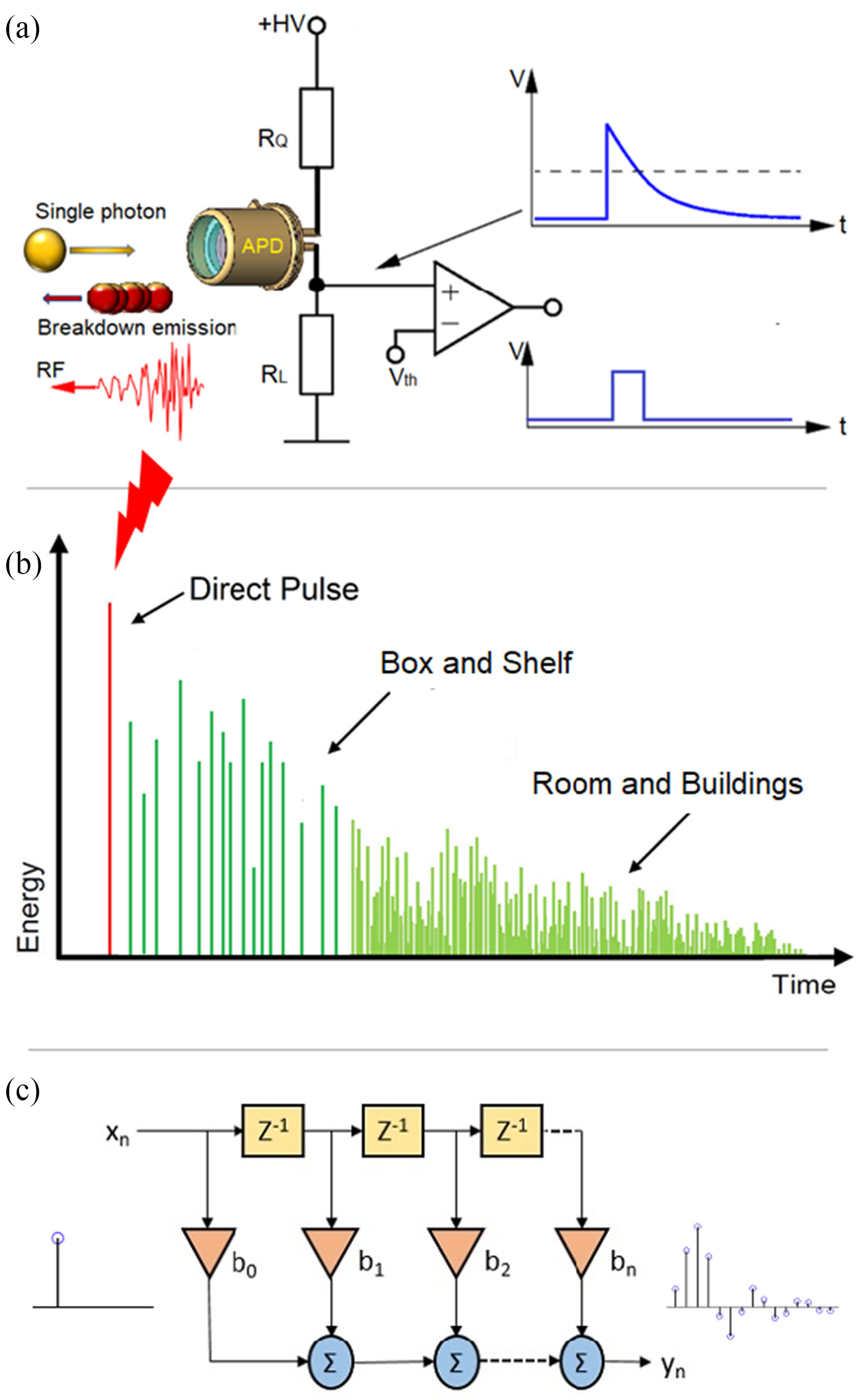
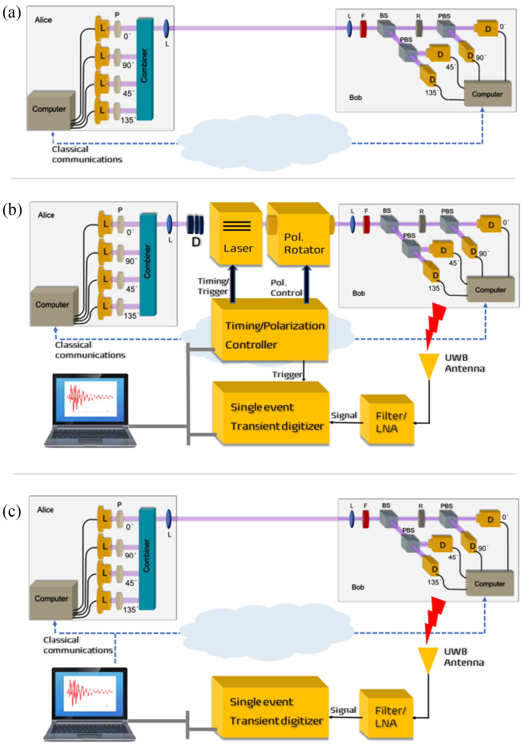
The neural network in Fig. 8 takes a time-domain sample of 256 data points, and can be trained to classify a test sample into one of four polarisation states at high accuracy.

Fig. 8: A 5-layer neural network with 256 input neurons and 2 output neurons (encoding 2 bits of information) [DJK22, Fig. 7].

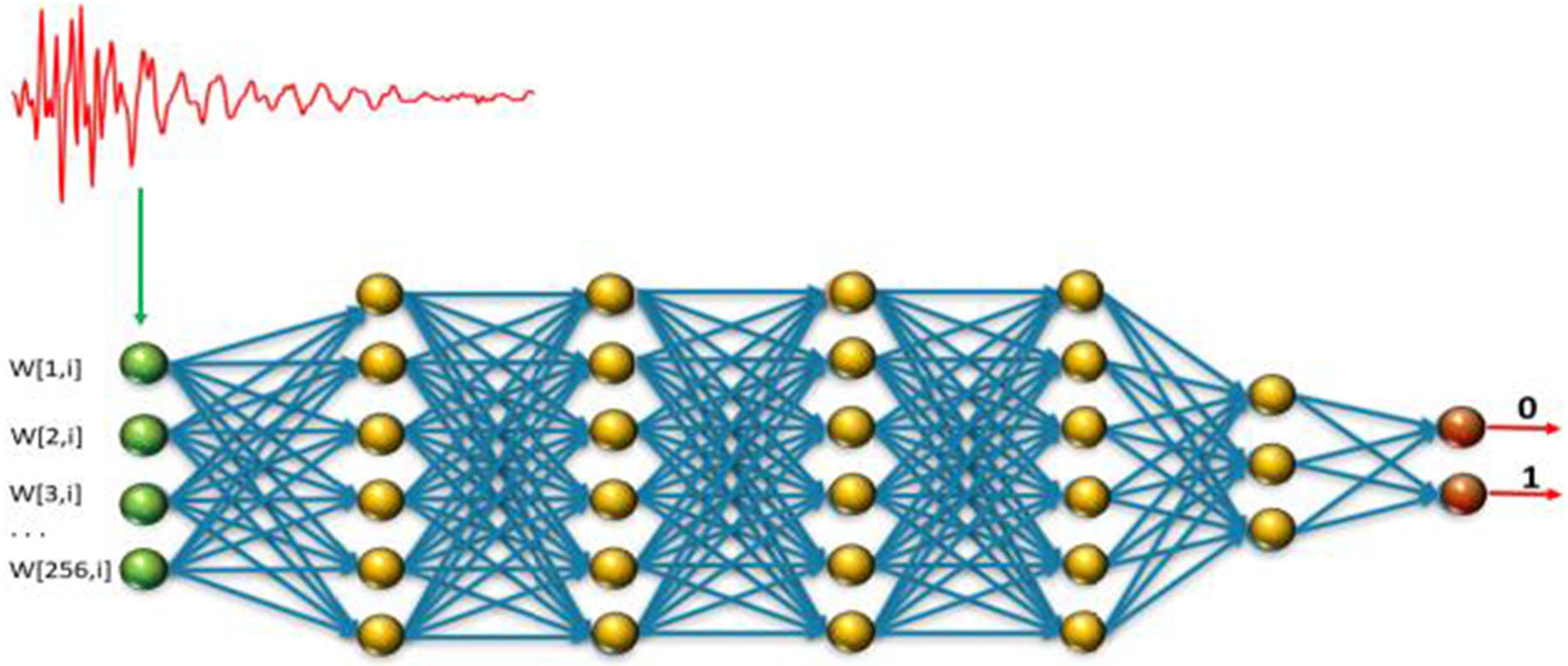
Durak et al.’s [DJK22] results demonstrate feasibility of “cloning” Bob’s qubits using an RF side channel.

Countermeasures

The countermeasures for CWE-1300 apply.

References

[BB84] C. H. Bennett and G. Brassard, Quantum cryptography: Public key distribution and coin tossing, in Proceedings of the International Conference on Computers, Systems & Signal Processing, December 1984, pp. 175–179. Available at https://arxiv.org/abs/2003.06557.
[DJK22] K. Durak, N. C. Jam, and S. Karamzadeh, Attack to quantum cryptosystems through RF fingerprints from photon detectors, IEEE Journal of Selected Topics in Quantum Electronics 28 no. 2: Optical Detectors (2022), 1–7. https://doi.org/10.1109/JSTQE.2021.3089638.
[ETS18] ETSI, Quantum Key Distribution (QKD); Vocabulary, Group Report ETSI GR QKD 007 v1.1.1, December 2018. Available at https://www.etsi.org/deliver/etsi_gr/QKD/001_099/007/01.01.01_60/gr_qkd007v010101p.pdf.
[GGF17] P. A. Grassi, M. E. Garcia, and J. L. Fenton, Digital identity guidelines, NIST Special Publication 800-63-3, June 2017. https://doi.org/10.6028/NIST.SP.800-63-3.
[GZBE20] M. Guri, B. Zadov, D. Bykhovsky, and Y. Elovici, PowerHammer: Exfiltrating data from air-gapped computers through power lines, IEEE Transactions on Information Forensics and Security 15 (2020), 1879–1890. https://doi.org/10.1109/TIFS.2019.2952257.
[Shi07] R. Shirey, Internet Security Glossary, Version 2, IETF RFC 4949, 2007.

Picture of Yee Wei Law

Solar System Internetwork (SSI)

by Yee Wei Law - Thursday, 7 March 2024, 3:16 PM
 

The discussion below provides some historical context, an overview and a description of the network protocol stack of the Solar System Internetwork (SSI).

History

In 1999, the Interagency Operations Advisory Group (IOAG) was established to achieve cross support across the international space community and to expand the enabling levels of space communications and navigation interoperability [CCS14, Foreword].

In 2007, the IOAG chartered a Space Internetworking Strategy Group (SISG) to reach international consensus on a recommended approach for transitioning the participating agencies towards a future network-centric era of space mission operations [CCS14, Foreword].

In 2008, the SISG released a preliminary report on their operations concept for a Solar System Internetwork (SSI) [CCS14, Foreword]; see the 2011 conference version of the report [EDB11].

In 2010, the IOAG finalised the SSI Operations Concept and asked the Consultative Committee for Space Data Systems (CCSDS) to create the SSI architectural definition [CCS14, Foreword].

In 2014, the CCSDS Space Internetworking Services - Delay-Tolerant Networking (SIS-DTN) working group released the official informational report [CCS14].

The SSI architecture is based on international standards and voluntary agreements [CCS14, Executive Summary].

Participation in the SSI is expected to be incremental, and furthermore, the SSI specification and technologies are still evolving.

In fact, the Interplanetary Networking Special Interest Group (IPNSIG), a chapter of the Internet Society, has the vision to develop a secure and robust Solar System Internet, by extending networking to space, from the historical point-to-point, “bent pipe” communication architecture to a store-and-forward, packet-switched design, interconnecting any number of terrestrial and space-borne nodes [KCB+21].

Overview

The fundamental objective of the SSI is to provide automated and internetworked data communication services for space ventures (at least across the solar system) [CCS14, Executive Summary; EDB11, Sec. 2].

The emphasis on automation arises from the need to support communication among the various participants operating in space ventures without requiring a detailed understanding of space communication operations [CCS14, Executive Summary].

Examples of participants include [CCS14, Sec. 2.1]:

  • crewed and robotic space-faring vehicles, often carrying investigative instruments;
  • planetary surface systems, with crew and/or instruments;
  • ground antenna stations;
  • centralised ground-based mission operations centres (MOCs) on Earth;
  • science investigators at widely distributed laboratories on Earth.

The SSI interconnects multiple networks built on two types of networking architectures, namely 1️⃣ the Internet architecture and 2️⃣ the DTN architecture.

Fig. 1 depicts a communication scenario that the SSI architecture is designed to support.

Fig. 1: A sample communication scenario involving two agencies and three missions [CCS14, Figure 2-3].

In Fig. 1,

  • Multiple missions may be involved, and each mission may operate multiple spacecrafts, which may autonomously collaborate on mission objectives.
  • The set of spacecrafts conducting a long-lived mission may change over time, as disabled spacecrafts become decommissioned and new spacecrafts get deployed.
  • Data may be routinely relayed among spacecrafts, even among spacecrafts deployed for different missions, by different space agencies. Furthermore, data may be relayed through different spacecrafts at different times, introducing the possibility of multiple data paths between spacecrafts and MOCs.

To accommodate the multi-agency, multi-mission scenario in Fig. 1, the SSI architecture specifies three stages of functionality:

Protocol stack

The SSI protocol stack is a combination of the Internet Protocol (IP) stack and the Delay-Tolerant Network (DTN) protocol stack, as shown in Fig. 2.

Going top-down along the DTN “facet” (CCSDS term) [CCS14, Sec. C3],

  • DTN applications are applications designed to operate with communications characterised by variable, substantial latencies due to 1️⃣ large signal propagation delays, 2️⃣ lengthy physical communication outages, or 3️⃣ both.

    These applications are implemented to utilise the CCSDS File Delivery Protocol (CFDP) and optionally other DTN application-layer services over a Bundle Protocol (BP) network.

Fig. 2: The composite network protocol stack of the SSI [CCS14, Figure C-9].

Fig. 3: A sample instantiation of the CCSDS protocol stack [CCS20d, Figure 2-1], where CLA = convergence layer adapter.

  • The BP network runs over the Licklider Transmission Protocol (LTP).

    While protocols from the IP suite are limited to scenarios in which network paths are continuously connected and have low latencies, BP network can operate in any scenario in the SSI, including on top of TCP/IP, as Fig. 3 shows.

  • Fig. 3 also shows below the LTP layer, sit the Encapsulation Packet Protocol and Space Packet Protocol.

    The Space Data Link Protocols (SDLPs) sit further down the protocol stack.

  • Among the SDLPs, the Proximity-1 Space Link Protocol is defined for short-range, bi-directional, fixed or mobile radio links, generally used to communicate among probes, landers, rovers, orbiting constellations, and orbiting relays.

    The 1️⃣ Telecommand (TC) SDLP, 2️⃣ Telemetry (TM) SDLP, and 3️⃣ Advanced Orbital Systems (AOS) SDLP [CCS15d] serve other scenarios.

    Fig. 4 demonstrates the usage of AOS-SDLP in a space network and Proximity-1 in a Mars network.

    Fig. 5 demonstrates the usage of Proximity-1 between two space nodes; and the usage of AOS-SDLP and TC-SDLP between a space node and a ground terminal.

    Improving upon the preceding protocols, the Unified Space Data Link Protocol (USLP, not typo) has been designed to meet the requirements of space missions for efficient transfer of space application data of various types and characteristics over space-to-ground, ground-to-space, and space-to-space communications links [CCS21c].

    Fig. 6 maps the protocols discussed so far to the Open System Interconnection (OSI) model.

Fig. 4: An example of how CCSDS protocols are used in a scenario where lander data are transferred using custody transfer to the lander MOC on Earth [ABH21, Figure 9].

Fig. 5: DTN protocol building blocks in an end-to-end ABCBA view [CCS18, Figure 3-3].

In CCSDS terminology [CCS15b, Sec. 1.6.1], an ABCBA view/configuration refers to a multi-hop space communications configuration involving 1️⃣ multiple space and ground elements and 2️⃣ multiple direct earth-space and space-space links. ABCBA configurations nominally include elements from three or more agencies.

Fig. 6: CCSDS protocols and associated security options [CCS19b, Figure 3-1], where SBSP = Streamlined Bundle Security Protocol, SDLS = Space Data Link Security.

References

[ABH21] A. Y. Alhilal, T. Braud, and P. Hui, A roadmap toward a unified space communication architecture, IEEE Access 9 (2021), 99633–99650. https://doi.org/10.1109/ACCESS.2021.3094828.
[CCS14] CCSDS, Solar System Internetwork (SSI) Architecture, Informational Report CCSDS 730.1-G-1, The Consultative Committee for Space Data Systems, July 2014. Available at https://public.ccsds.org/Pubs/730x1g1.pdf.
[CCS15b] CCSDS, Space Communications Cross Support—Architecture Requirements Document, Recommended Practice CCSDS 901.1-M-1, The Consultative Committee for Space Data Systems, May 2015. Available at https://public.ccsds.org/Pubs/901x1m1.pdf.
[CCS15d] CSDS, Space Data Link Protocols—Summary of Concept and Rationale, Informational Report CCSDS 130.2-G-3, The Consultative Committee for Space Data Systems, September 2015. Available at https://public.ccsds.org/Pubs/130x2g3.pdf.
[CCS18] CCSDS, Concepts and Rationale for Streaming Services over Bundle Protocol, Informational Report CCSDS 730.2-G-1, The Consultative Committee for Space Data Systems, September 2018. Available at https://public.ccsds.org/Pubs/730x2g1.pdf.
[CCS19b] CCSDS, The Application of Security to CCSDS Protocols, Informational Report CCSDS 350.0-G-3, The Consultative Committee for Space Data Systems, March 2019. Available at https://public.ccsds.org/Pubs/350x0g3.pdf.
[CCS20d] CCSDS, Space Packet Protocol, Recommended Standard CCSDS 133.0-B-2, The Consultative Committee for Space Data Systems, June 2020. Available at https://public.ccsds.org/Pubs/133x0b2e1.pdf.
[CCS21c] CCSDS, Unified Space Data Link Protocol, Recommended Standard CCSDS 732.1-B-2, The Consultative Committee for Space Data Systems, October 2021. Available at https://public.ccsds.org/Pubs/732x1b2.pdf.
[EDB11] C. D. Edwards, M. Denis, and L. Braatz, Operations concept for a Solar System Internetwork, in 2011 Aerospace Conference, 2011, pp. 1–9. https://doi.org/10.1109/AERO.2011.5747340.
[KCB+21] Y. Kaneko, V. Cerf, S. Burleigh, M. Luque, and K. Suzuki, Strategy toward Solar System Internet for humanity, Report from Strategy Working Group, Interplantery Networking Special Interest Group, Internet Society, June 2021. Available at https://ipnsig.org/wp-content/uploads/2021/10/IPNSIG-SWG-REPORT-2021-3.pdf.
[WZP18] P. Wan, Y. Zhan, and X. Pan, Solar system interplanetary communication networks: architectures, technologies and developments, Science China Information Sciences 61 no. 4 (2018), 040302. https://doi.org/10.1007/s11432-017-9346-1.

Picture of Yee Wei Law

Solar System Internetwork (SSI) Stage 1 Mission Functionality

by Yee Wei Law - Tuesday, 16 May 2023, 11:55 AM
 

This continues from Solar System Internetwork (SSI).

The Stage 1 Mission Functionality of the Solar System Internetwork (SSI) is the automation of basic communication processes between vehicles and Mission Operations Centers (MOCs) that might be performed for a single space flight mission, including [CCS14, Sec. 3]:

  • the initiation and termination of transmissions;
  • the scheduling of data for transmission according to priority designations declared by SSI users;
  • the segmentation and reassembly of large data items for transmission in small increments;
  • the retransmission of data that were lost or corrupted in transmission;
  • the relaying of data from one entity to another via some other entity pre-selected by management.

Fig. 1 depicts a sample communication scenario between two SSI nodes: one onboard the spacecraft and another at the spacecraft MOC.

  • The SSI data flow between these two nodes is established by requesting a space link session from the Earth station control center.
  • Data are exchanged via the Earth station by link-layer mechanisms, which are nominally based on the CCSDS Space Link Extension (SLE) service [CCS13].
Fig. 1: Sample communication scenario in a simple network topology [CCS14, Figure 3-1].

The network configuration in Fig. 1 can be extended by setting up a separate SSI node for use by the instrument MOC, enabling the instrument MOC to operate on native instrument data flows securely routed through the node at the spacecraft MOC.

Prerequisites and protocols

To be part of the SSI, each node must be configured to run the Bundle Protocol (BP), i.e., a Bundle Protocol Agent (BPA) must be deployed at each node.

For each node on the Earth surface, a Convergence-Layer Adapter (CLA) must be deployed underneath BP, enabling the node to communicate with other Earth-bound nodes via the Internet.

For interoperation with the Internet, the CLA can use the Transmission Control Protocol (TCP) and User Datagram Protocol (UDP), or potentially the Licklider Transmission Protocol (LTP) running on top of UDP/Internet Protocol (IP).

References

[CCS13] CCSDS, Space Communications Cross Support—Architecture Description Document, Informational Report CCSDS 901.0-G-1, The Consultative Committee for Space Data Systems, November 2013.
[CCS14] CSDS, Solar System Internetwork (SSI) Architecture, Informational Report CCSDS 730.1-G-1, The Consultative Committee for Space Data Systems, July 2014.

Picture of Yee Wei Law

Space Attack Research and Tactic Analysis (SPARTA)

by Yee Wei Law - Wednesday, 1 March 2023, 5:19 PM
 

The Aerospace Corporation created the Space Attack Research and Tactic Analysis (SPARTA) cybersecurity matrix

  • to address the information and communication barriers that hinder the identification and sharing of space-cyber Tactic, Techniques, and Procedures (TTP);
  • to provide unclassified information to space professionals about cyber threats to spacecraft.

The SPARTA matrix is a specialisation of the MITRE ATT&CK matrix for defining and categorising commonly identified activities that contribute to spacecraft compromises.

The nine SPARTA tactics shown in the top row of Fig. 1 are a subset of the tactics in MITRE ATT&CK.

Fig. 1: The main attack tactics and techniques in SPARTA. Every technique accompanied by a double vertical sign, ⏸, expands into sub-techniques not shown here.

Under each SPARTA tactic in Fig. 1, each of the main techniques accompanied by a double vertical sign, namely ⏸, can be divided into sub-techniques. For example, under tactic “Reconnaissance” (ST0001), the technique “Gather Spacecraft Design Information” (REC-0001) can be divided into 1️⃣ Software (REC-0001.01), 2️⃣ Firmware (REC-0001.02), 3️⃣ Cryptographic Algorithms (REC-0001.03), 4️⃣ Data Bus (REC-0001.04), 5️⃣ Thermal Control System (REC-0001.05), 6️⃣ Manoeuvre and Control (REC-0001.06), 7️⃣ Payload (REC-0001.07), 8️⃣ Power (REC-0001.08), and 9️⃣ Fault Management (REC-0001.09).

Example 1: Payload

The South Australian 6U CubeSat Kanyini has two payloads: 1️⃣ a hyperspectral imager called HyperScout 2 for earth observation, and 2️⃣ an Internet-of-Things communications module.

Example 2: Applying SPARTA to modelling a recent cyber attack

Watch a quick overview of the attack called PCspooF:

A mixed-criticality system (MCS) is an embedded computing platform in which application functions of different criticalities share computation and/or communication resources [EDN16].

A mixed time-criticality system is an MCS where the criticality is messaging timeliness.

Time-Triggered Ethernet (TTEthernet), as standardised in SAE AS6802, defines algorithms for clock synchronisation, clique detection, startup, and restart for switches and end systems to achieve fault-tolerant synchronisation in an Ethernet-based (IEEE 802.3) mixed time-criticality system.

TTEthernet is used in avionics, industrial control systems (including those for power systems) and automotive systems [LPDK23], so any security vulnerability in TTEthernet would have wide-reaching consequences.

  • In avionics, TTEthernet is used as a bus service for a variety of spacecraft including NASA’s Orion capsule, NASA’s Lunar Gateway space station, and ESA’s Ariane 6 launcher [The22].

How TTEthernet works [LPDK23]

A TTEthernet network contains two types of devices: switches and end systems.

Fault-tolerance is enabled by network redundancy, and each redundant network is called a plane; Fig. 2 shows an example of a system using two planes.

Time-triggered (TT) design = All TTEthernet devices are tightly synchronised and the behaviour of the network is determined by a global schedule made offline and loaded onto each TTEthernet device before deployment.

Fig. 2: TTEthernet provides redundancy to ESA’s Ariane 6 launcher [Fid15, slide 19].
Fig. 3: In TTEthernet, TT traffic is synchronous with sub-microsecond jitters, whereas BE traffic and rate-constrained traffic are asynchronous  [Fid15, slide 16].

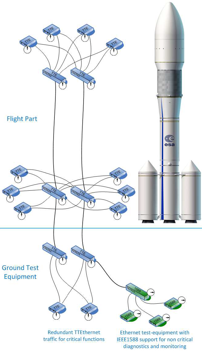
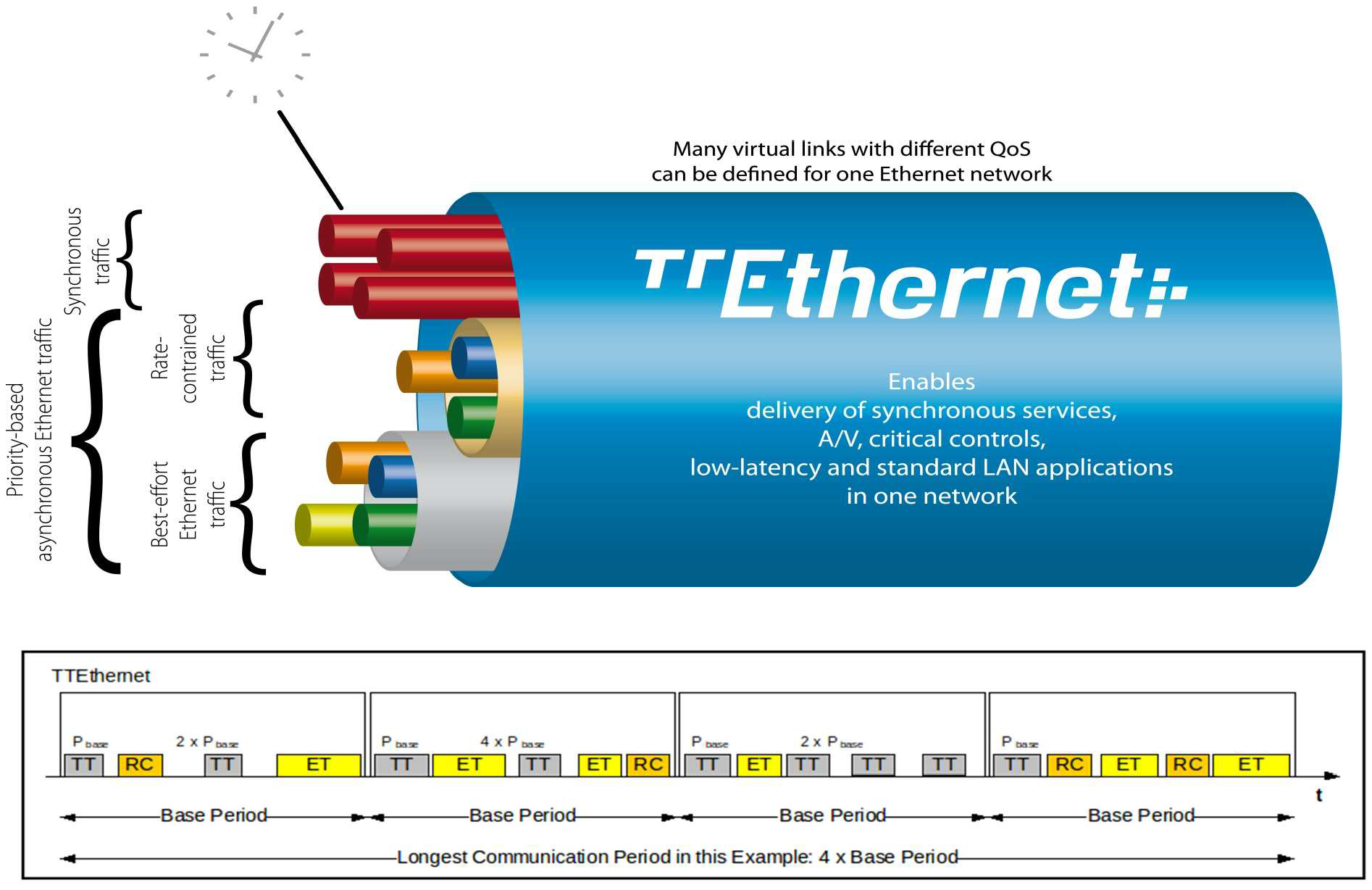
The global schedule specifies when TT frames are forwarded and expected to arrive.

The latency and jitter of TT traffic can be reduced to below 13 μs and 1 μs respectively [Fid15, slide 12].

TTEthernet also carries best-effort (BE, i.e., regular) Ethernet traffic and rate-constrained Avionics Full Duplex Switched Ethernet (AFDX, as standardised in ARINC Specification 664 P7-1) traffic; see Fig. 3.

TTEthernet switches forward BE traffic around the pre-scheduled TT traffic when bandwidth permits.

Mechanisms exist to isolate TT traffic from BE traffic, e.g.,

  • there are windows reserved for TT traffic only;
  • TT and BE frames are stored in different switch buffers.

Central to TTEthernet is a synchronisation protocol, in which a device can participate as 1️⃣ a sync master, 2️⃣ a compression master, or 3️⃣ a sync client.

  • Typically, a subset of the end systems serve as sync masters, while 1-2 switches per plane serve as compression masters.
  • The remaining devices serve as sync clients.

Devices exchange protocol control frames (PCFs) every integration cycle.

  • At the beginning of each integration cycle, every sync master sends a PCF containing its local clock value to the compression masters.
  • The compression masters average the received clock values, then send out the average in a new PCF to the sync masters and clients, which then correct their local clocks.

Receiving certain PCFs from a compression master can cause sync masters and clients to lose synchronisation.

  • An example of such PCFs is “coldstart acknowledgement”, which tells a sync master another sync master detected loss of synchronisation and is reestablishing it.
  • Since a PCF can cause de-synchronisation, TTEthernet requires each compression master to be a self-checking pair, which only produces a PCF if two independent processors agree on the contents.

Attacker/threat model for PCspooF

The PCspooF attack is feasible provided:

  • Attacker has access to at least one BE device, e.g.,
    • by supplying such a device (as a malicious supplier) for integration into the TTEthernet network before the network is deployed;
    • by connecting the device to the TTEthernet network after the network has been deployed.
  • Attacker can control the BE device operating in one plane; see Fig. 4.
  • Attacker-controlled BE device includes additional circuit components for conducting electromagnetic interference (EMI) through its Ethernet cable into a switch; see Fig. 5.
Fig. 4: Attacker controls one BE device in one plane [LPDK23, Fig. 1].
Fig. 5: Rogue BE device injects PCFs via EMI [LPDK23, Fig. 3].

The PCspooF attack

PCspooF is a cyber-physical attack that attempts to disrupt the TTEthernet synchronisation protocol by spoofing PCFs, and thereby inflict denial of service on its victim.

The attack happens in two stages:

  • Stage 1️⃣: This is the cyber stage, where the attacker fabricates a valid PCF.

    Fig. 6: (Top) Standard Ethernet frame vs (Bottom) TTEthernet frame [Lov15, Fig. 3].

    A PCF has the same structure as a standard minimum-sized Ethernet frame, but instead of a destination MAC address, it has a 4-byte Critical Traffic Marker (a special value used to identify all PCFs and TT traffic) and a 2-byte Virtual Link ID (also called Critical Traffic ID [Lov15], which identifies the source of a PCF); see Fig. 6.

    These two fields 👆 must match the values specified in the network schedule loaded onto the TTEthernet devices. These two fields happen to be the only fields that pose a challenge to spoof.

    Skipping the details [LPDK23, Sec. IIIA], an attacker can determine valid Critical Traffic Markers by abusing the Address Resolution Protocol and trying a maximum of around one billion possible values.

    Skipping the details again [LPDK23, Sec. IIIA], an attacker can try to use 4071 or 4070 as the Virtual Link ID, or in the worst case, try a maximum of 65536 values.

    The fabricated PCF is stored inside the payload of a benign BE frame, because TTEthernet switches drop PCFs from BE devices.

    The next stage is to trick a switch into forwarding the aforementioned BE frame as a PCF.

  • Stage 2️⃣: This is the physical stage, where the attacker uses EMI to convert a BE frame into a PCF during transmission.

    This is an example of a link reset attack, which in turn is an example of a packet-in-packet attack [GBM+11].

    Scenario: a BE device is transmitting to a switch, but the PHY preamble becomes corrupted, and consequently the PHY layer of the switch resets itself.

    Attacker uses the opportunity to send packet below:

    Fig. 7: Link reset attack, a type of packet-in-packet attack, uses a long preamble and embeds a malicious packet in a trojan packet [LPDK23, Fig. 5].

    In Fig. 7, the PHY layer and outgoing port of the switch recover during the transmission of the fake preamble.

    Result: Inner frame, which contains the fake PCF, gets sent.

    Corruption of PHY preamble can be achieved through EMI; see Figs. 8-9.

    Fig. 8: Common-mode voltage surge on an Ethernet twisted pair can cause EMI in spite of inductive/magnetic isolation [LPDK23, Fig. 6].
    Fig. 9: Implementing common-mode voltage surge and thereby EMI using an NPN BJT and a spark gap [LPDK23, Fig. 7].

Applying SPARTA

Using the language of SPARTA, these attack stages can be identified [The22]: 1️⃣ Reconnaissance, 2️⃣ Resource Development, 3️⃣ Initial Access, 4️⃣ Execution, 5️⃣ Lateral Movement, 6️⃣ Impact

Table 1 and Table 2 map these attack stages to the attack steps in PCspooF.

Table 1: The first three stages of PCspooF.
Reconnaissance (ST0001) Resource Development (ST0002) Initial Access (ST0003)
  • Gather Spacecraft Design Information (REC-0001), and specifically, Data Bus (REC-0001.04):

    😈 Attacker gathers information required for successful spoofing of TTEthernet frame fields (e.g., Critical Traffic Marker, Virtual Link ID) and design of EMI-injecting PCB.

  • Gather Supply Chain Information (REC-0008), and specifically, Hardware (REC-0008.01):

    😈 Attacker gathers information on the hardware in use, e.g., TTEthernet utilisation, EMI target.

  • Eavesdropping (REC-0005):

    😈 Attacker eavesdrops on the network to infer valid Critical Traffic Markers and Virtual Link IDs from devices’ responses or lack of response.

  • Stage Capabilities (RD-0004), and specifically, Identify/Select Delivery Mechanism (RD-0004.01):

    😈 Attacker identifies the ideal BE device to use for executing the attack.

  • Compromise Supply Chain (IA-0001), and specifically, Hardware Supply Chain (IA-0001.03):

    😈 Attacker sneaks the attacking BE device into the supply chain before or after the deployment of the targeted TTEthernet network.

  • Auxiliary Device Compromise (IA-0011):

    😈 Attacker investigates potential use of a USB/generic hardware vector instead of a BE device.

Table 2: The last three stages of PCspooF.
Execution (ST0004) Lateral Movement (ST0007) Impact (ST0009)
  • Time Synchronised Execution (EX-0008):

    😈 Attacker implements a “ticking timebomb” trigger, which activates attack after a preset amount of post-deployment time.

  • Flooding (EX-0013), and specifically, Erroneous Input (EX-0013.02):

    😈 Attacker brute-forces ARP requests and emissions of EMI.

  • Exploit Hardware/Firmware Corruption (EX-0005), and specifically, Design Flaws (EX-0005.01):

    😈 Attacker exploits weaknesses permitting aggressive ARP polling of BE devices, gathering of information (e.g., Critical Traffic Markers, Virtual Link IDs), and link reset attacks for spoofing PCFs (see Fig. 7).

  • Spoofing (EX-0014), and specifically, Bus Traffic (EX-0014.02):

    😈 Attacker injects spoofed PCFs via EMI-based link reset attacks.

  • Exploit Lack of Bus Segregation (LM-0002):

    😈 Attacker is enabled by the situation where critical (TT) and non-critical (BE) components share the same physical networking infrastructure to use a non-critical component (BE device) to disrupt the operations of critical components (TT devices).

  • Disruption (IMP-0002):

    😈 TTEthernet synchronisation broken, critical operations not being performed, leading to disruption of critical spacecraft operations (e.g., manoeuvring, sensing, communications) and overall mission.

References

[EDN16] R. Ernst and M. Di Natale, Mixed criticality systems—a history of misconceptions?, IEEE Design & Test 33 no. 5 (2016), 65–74. https://doi.org/10.1109/MDAT.2016.2594790.
[Fid15] C. Fidi, Time-Triggered Ethernet: CCSDS Meeting, slides, March 2015. Available at https://cwe.ccsds.org/sois/docs/SOIS-APP/Meeting%20Materials/2015/Spring/SOIS%20Plenary/2015-03-23_TTEthernet-Overview_V1.0.pdf.
[GBM+11] T. Goodspeed, S. Bratus, R. Melgares, R. Shapiro, and R. Speers, Packets in Packets: Orson Welles’ In-Band Signaling Attacks for Modern Radios, in WOOT’11: 5th USENIX Workshop on Offensive Technologies, 2011. Available at https://www.usenix.org/legacy/event/woot11/tech/final_files/Goodspeed.pdf.
[Lov15] A. Loveless, On TTEthernet for Integrated Fault-Tolerant Spacecraft Networks, in AIAA SPACE 2015 Conference and Exposition, 2015. https://doi.org/10.2514/6.2015-4526.
[LPDK23] A. Loveless, L. Phan, R. Dreslinski, and B. Kasikci, PCspooF: Compromising the Safety of Time-Triggered Ethernet, in 2023 IEEE Symposium on Security and Privacy, IEEE Computer Society, Los Alamitos, CA, USA, May 2023, pp. 572–587. https://doi.org/10.1109/SP46215.2023.00033.
[The22] The Aerospace Corporation, Introducing SPARTA using PCSpooF: Cyber Security for Space Missions, Medium, December 2022. Available at https://aerospacecorp.medium.com/sparta-cyber-security-for-space-missions-4876f789e41c.

Picture of Yee Wei Law

Space Packet Protocol (SPP)

by Yee Wei Law - Saturday, 27 May 2023, 3:51 PM
 

Introduction

In many space applications, it is desirable to have a single, common application-layer data structure for the creation, storage, and transport of variable-length application-layer data.

These data is expected to be 1️⃣ exchanged and stored on board, 2️⃣ transferred over one or more space data links, and 3️⃣ used within ground systems.

It is often necessary to identify the 1️⃣ type, 2️⃣ source, and/or 3️⃣ destination of these data.

The preceding needs motivate the definition of the Space Packet Protocol (SPP).

The SPP is designed as a self-delimited carrier of a data unit — called a Space Packet — that contains an application process identifier (APID) used to identify the data contents, data source, and/or data user within a given enterprise [CCS20d, Sec. 2.1.1].

Fig. 1 shows where the SPP sits in the CCSDS protocol stack.

Fig. 2 shows a communication scenario between a spacecraft and a ground terminal, where the SPP plays an important role.

Fig. 1: The SPP sits above the data link layer and below the upper layers in the CCSDS protocol stack [CCS20d, Figure 2-1], where CLA = convergence layer adapter.

Fig. 2: A sample communication scenario [CCS20a, Figure 9-12], featuring mission operations (MO) applications residing in the spacecraft’s onboard computer (OBC).

All OBC apps are under the control of a real-time operating system (RTOS); with the striped blocks running in hard real time.

Science operations (SO) functions are executed through Message Transfer Service, File and Packet Store Services, etc.

The yellow blocks represent the spacecraft onboard interface services (SOIS), and the SPP is one of these services.

Between the SPP and the MO applications sits the Message Abstraction Layer (MAL) [CCS13a], an important component of CCSDS’s Missions Operations Framework.

For applications on separate onboard computers, communications pass through the whole stack and use the physical subnetwork to communicate.

For applications on the same computer, communications pass through the stack to a local loopback function in the software bus.

APID

APIDs are unique in a single naming domain [CCS20d, Sec. 2.1.3]

An APID naming domain usually corresponds to a spacecraft, or an element of a constellation of space vehicles.

Every space project allocates the APIDs to be used in a naming domain.

More precisely, the space project assigns APIDs to managed data paths within a naming domain.

Open-source implementations

The following open-source implementations are known at the time of writing:

References

[CCS13a] CCSDS, Mission Operations Message Abstraction Layer, Recommended Standard CCSDS, The Consultative Committee for Space Data Systems, March 2013. Available at https://public.ccsds.org/Pubs/521x0b2e1.pdf.
[CCS20a] CCSDS, Application and Support Layer Architecture, Informational Report CCSDS 371.0-G-1, The Consultative Committee for Space Data Systems, November 2020. Available at https://public.ccsds.org/Pubs/371x0g1.pdf.
[CCS20d] CCSDS, Space Packet Protocol, Recommended Standard CCSDS 133.0-B-2, The Consultative Committee for Space Data Systems, June 2020. Available at https://public.ccsds.org/Pubs/133x0b2e1.pdf.

Picture of Yee Wei Law

Spectre attacks

by Yee Wei Law - Monday, 3 April 2023, 11:34 AM
 

The Spectre attacks exploit the weakness CWE-1037 “Processor Optimization Removal or Modification of Security-critical Code”.

Modern processors use branch prediction and speculative execution to maximise performance, but the implementations of these optimisations in many processors were found to have broken a range of software security mechanisms, including operating system process separation, containerisation, just-in-time (JIT) compilation, and countermeasures to cache timing and side-channel attacks [KHF+20].

Watch the presentation given by one of the discoverers of Spectre attacks at the 40th IEEE Symposim on Security and Privacy:

More information on the Meltdown and Spectre website.

References

[KHF+20] P. Kocher, J. Horn, A. Fogh, D. Genkin, D. Gruss, W. Haas, M. Hamburg, M. Lipp, S. Mangard, T. Prescher, M. Schwarz, and Y. Yarom, Spectre attacks: Exploiting speculative execution, Commun. ACM 63 no. 7 (2020), 93 – 101. https://doi.org/10.1145/3399742.

Picture of Yee Wei Law

Spread spectrum and frequency hopping

by Yee Wei Law - Wednesday, 24 May 2023, 11:26 AM
 

Frequency hopping is one of two main spread spectrum techniques.

Spread spectrum

A spread-spectrum signal is a low-probability-of-intercept (LPI) signal with extra modulation that expands the signal bandwidth greatly beyond what is required by the underlying channel code (e.g., low-density parity-check codes) and modulation [Tor18].

High-level idea [Ada01, pp. 123-124]:

  • Sender modulates its signal such that signal energy is spread in frequency, and the resultant frequency spectrum is orders of magnitude wider than the information bandwidth (i.e., what is required to carry the signal’s information).
  • A synchronisation scheme exists between the sender and the intended receiver that enables the intended receiver to remove the spreading modulation and process the received signal in the information bandwidth; see Fig. 1.
  • Unintended receivers without knowledge of the synchronisation scheme cannot narrow the signal bandwidth and recover the original signal due to the low signal-to-noise ratio.
Fig. 1: Spread-spectrum signals are broadcast with much wider bandwidth than the information bandwidth [Ada01, Figure 7-1]. The intended receiver can reduce the bandwidth to the information bandwidth, whereas the unintended receivers cannot.

Spread-spectrum communication systems are useful for 1️⃣ suppressing interference, 2️⃣ making secure communications difficult to detect and process, 3️⃣ accommodating fading and multipath channels, and 4️⃣ providing multiple-access capability.

Spread-spectrum signals cause relatively minor interference to other systems operating in the same spectral band.

Two dominant spread-spectrum systems: 1️⃣ direct-sequence and 2️⃣ frequency-hopping.

Frequency-hopping spread spectrum (FHSS)

Intuition: If using one communication channel allows our adversary to sense our channel and subsequently jam it, then it would make sense for us to hop 🐇 from one channel to channel in such a way that it is hard to detect.

The sequence of carrier frequencies is called the frequency-hopping pattern; see Fig. 2.

The set of possible carrier frequencies is called the hopset.

Each of the frequency channel is defined as a spectral region that 1️⃣ includes a single carrier frequency of the hopset as its centre frequency and 2️⃣ has a bandwidth large enough to include most of the power in a single pulse.

The rate at which the carrier frequency changes is the hop rate.

The time interval between hops is the hop interval, and its length is called hop duration ( in Fig. 2).

Fig. 2: A sample frequency-hopping pattern with hop duration and hopping bandwidth [Tor18, Fig. 3.1].

The frequency band within which hopping occurs is the hopping band, and its bandwidth is called hopping bandwidth ( in Fig. 2).

Figs. 3-4 show the general form of a frequency-hopping transmitter and the general form of a frequency-hopping (FH) receiver respectively.

Fig. 3: The general form of an FH transmitter [Tor18, Fig. 3.2a].

Fig. 4: The general form of an FH receiver [Tor18, Fig. 3.2b].

On the transmitter end in Fig. 3, the pattern generator generates a set of pattern-control bits at the hop rate.

The frequency synthesiser synthesises an FH pattern based on the pattern-control bits.

To ensure that an FH pattern is difficult to reproduce or dehop by an adversary, the pattern should be 1️⃣ pseudorandom with a large period and 2️⃣ as uniformly distributed over the frequency channels as possible.

The data-modulated signal is mixed with the FH pattern to produce the FH signal.

On the receiver end in Fig. 4, the same FH pattern on the transmitter end is replicated here in synchrony.

The mixing operation, called dehopping, removes the FH pattern from the received signal.

The bandpass filter removes the double-frequency components and produces the data-modulated dehopped signal.

Example 1

An example of commercial transceivers that support FHSS is Murata’s DNT24 series of 2.4 GHz FHSS wireless transceivers [Wil14].

These transceivers support the establishment of a store-and-forward (i.e., delay-tolerant) network (see Fig. 5), which consists of a base node connected to router nodes, which are in turn connected to remote nodes.

Fig. 5: An example of a store-and-forward network formed by DNT24 transceivers [Wil14, Figure 2.3.1].

For base nodes, the hop duration can range from 8 ms to 100 ms, and has the default value of 20 ms [Wil14, Sec. 7.4].

Other nodes synchronise their hop duration with the base.

Pros

Compared to direct-sequence spread spectrum (DSSS), FHSS 1️⃣ offers more resilience to interference, and is thus better suited for co-located systems; 2️⃣ enables higher channel utilisation [Wil14].

DSSS also requires more circuitry (higher cost) to implement, is more energy-consuming and more sensitive to environmental effects [Law05, Sec. 2.3.2].

Cons

However, FHSS systems require an initial acquisition period during which the receiver must lock on to the moving carrier of the transmitter before any data can be sent, which typically takes several seconds [Wil14].

References

[Ada01] D. Adamy, EW 101 - A First Course in Electronic Warfare, Artech House, 2001. Available at https://app.knovel.com/hotlink/toc/id:kpEWAFCEW7/ew-101-first-course-in/ew-101-first-course-in.
[Law05] Y. W. Law, Key management and link-layer security of wireless sensor networks: energy-efficient attack and defense, Ph.D. thesis, University of Twente, 2005. https://doi.org/10.3990/1.9789036522823.
[Tor18] D. Torrieri, Principles of Spread-Spectrum Communication Systems, fourth ed., Springer Cham, 2018. https://doi.org/10.1007/978-3-319-70569-9.
[Wil14] R. Willett, DNT24 Series, 2.4 GHz Spread Spectrum Wireless Transceivers, Integration Guide, 2014. Available at https://www.murata.com/-/media/webrenewal/products/connectivitymodule/asset/pub/rfm/data/dnt24_integration.ashx.

Picture of Yee Wei Law

Stream ciphers

by Yee Wei Law - Monday, 4 September 2023, 11:11 PM
 
See 👇 attachment or the latest source on Overleaf.
Tags:

Picture of Yee Wei Law

Systems Security Engineering

by Yee Wei Law - Tuesday, 7 March 2023, 3:21 PM
 

NIST provides guidelines on engineering trustworthy (see Definition 1) and cyber-resilient (see Definition 2) systems through NIST SP 800-160 volumes 1 and 2 [RWM22, RPG+21], to be used in conjunction with

  • ISO/IEC/IEEEE International Standard 15288:2015 [ISO15],
  • NIST SP 800-37 [Joi18] and
  • NIST SP 800-53 [Joi20].
Definition 1: Trustworthy [RWM22, p. 1]

Worthy of being trusted to fulfill whatever critical requirements may be needed for a particular component, subsystem, system, network, application, mission, enterprise or other entity.

Definition 2: Cyber-resilient [RPG+21, p. 1]

Able to anticipate, withstand, recover from, and adapt to adverse conditions, including stresses, attacks, and compromises on systems that use or are enabled by cyber resources.


📝 A cyber resource is an information resource which creates, stores, processes, manages, transmits, or disposes of information in electronic form and that can be accessed via a network or using networking methods; for example, a file or database.

A primary objective of NIST SP 800-160 volume 1 is to provide a basis for establishing a discipline for systems security engineering as part of systems engineering in terms of its principles, concepts, activities and tasks.

  • Systems engineering is a transdisciplinary and integrative approach to enabling the successful realisation, use, and retirement of engineered systems [RWM22, Sec. 2.2].
  • Systems security engineering is meant to provide complementary engineering capabilities that extend the concept of trustworthiness to deliver trustworthy systems [RWM22, p. 2].
  • Without going into details, Fig. 1 captures the workflow in the prescribed Systems Security Engineering Framework [RWM22, Sec. 4].
Fig. 1: The Systems Security Engineering Framework provides guidenlines on how to define the problem and how to develop a solution to achieve trustworthiness [RWM22, Fig. 10]. See [RWM22, Sec. 4] for details.

A primary objective of NIST SP 800-160 volume 2 is to provide guidance on how to apply cyber resilience concepts, constructs and engineering practices to systems security engineering and risk management for systems (e.g., enterprise IT, industrial control systems, Internet of Things) and organisations.

References

[ISO15] ISO, IEC and IEEE, ISO/IEC/IEEE International Standard 15288: Systems and software engineering – System life cycle processes, 2015. https://doi.org/10.1109/IEEESTD.2015.7106435.
[Joi18] Joint Task Force, Risk management framework for information systems and organizations: A system life cycle approach for security and privacy, NIST Special Publication 800-37 Revision 2, December 2018. https://doi.org/10.6028/NIST.SP.800-37r2.
[Joi20] Joint Task Force, Security and privacy controls for information systems and organizations, NIST Special Publication 800-53 Revision 5, September 2020. https://doi.org/10.6028/NIST.SP.800-53r5.
[RPG+21] R. Ross, V. Pillitteri, R. Graubart, D. Bodeau, and R. McQuaid, Developing cyberresilient systems: A systems security engineering approach, NIST Special Publication 800-160 Volume 2 Revision 1, December 2021. https://doi.org/10.6028/NIST.SP.800-160v2r1.
[RWM22] R. Ross, M. Winstead, and M. McEvilley, Engineering trustworthy secure systems, NIST Special Publication 800-160v1r1, November 2022. https://doi.org/10.6028/NIST.SP.800-160v1r1.

T

Picture of Yee Wei Law

Transport Layer Security

by Yee Wei Law - Sunday, 12 February 2023, 10:35 AM
 

TODO


Picture of Yee Wei Law

Trusted autonomy

by Yee Wei Law - Monday, 17 July 2023, 11:40 AM
 

Trusted Autonomy (TA) is a field of research that focuses on understanding and designing the interaction space between two entities each of which exhibits a level of autonomy [APM+16].

References

[APM+16] H. A. Abbass, E. Petraki, K. Merrick, J. Harvey, and M. Barlow, Trusted autonomy and cognitive cyber symbiosis: Open challenges, Cognitive Computation 8 no. 3 (2016), 385–408. https://doi.org/10.1007/s12559-015-9365-5.

Picture of Yee Wei Law

Type checking

by Yee Wei Law - Sunday, 14 May 2023, 5:08 PM
 

Type checking checks that program statements are well-formed with respect to a typing logic [vJ11, p. 1255].

For example, integers can be added and functions can be called, but integers cannot be called and functions cannot be added.

Type checking can be used to ensure programs are type-safe, meaning that at every step of the execution, all values have well-defined and appropriate types, and that there is a valid next step of execution.

References

[vJ11] H. C. van Tilborg and S. Jajodia (eds.), Encyclopedia of Cryptography and Security, Springer, Boston, MA, 2011. https://doi.org/10.1007/978-1-4419-5906-5.

U

Picture of Yee Wei Law

Universally composable security

by Yee Wei Law - Monday, 13 March 2023, 1:19 PM
 

First proposed by Canetti [Can01], the paradigm of universally composable security guarantees security even when a secure protocol is composed with an arbitrary set of protocols, or more generally when the protocol is used as a component of an arbitrary system.

  • It guarantees security even when an unbounded number of protocol instances are executed concurrently in an adversarially controlled manner.
  • It is an essential property for maintaining security of cryptographic protocols in complex and unpredictable environments such as the Internet.

References

[Can01] R. Canetti, Universally composable security: a new paradigm for cryptographic protocols, in Proceedings 42nd IEEE Symposium on Foundations of Computer Science, 2001, pp. 136–145. https://doi.org/10.1109/SFCS.2001.959888.

Picture of Yee Wei Law

USRP SDRs

by Yee Wei Law - Tuesday, 11 July 2023, 10:47 PM
 
Work in progress

Ettus’s wiki for B210.

Ettus’ wiki for X300/X310

Setting up UHD through Anaconda and GNU Radio.

Verifying operation.

PySDR: A Guide to SDR and DSP using Python, set up UHD following Ch. 6 (original instructions). Note highest Python version supported is 3.9. Use conda to save trouble.

Stuck at ldconfig:

/sbin/ldconfig.real: Can't link /usr/lib/wsl/lib/libnvoptix_loader.so.1 to libnvoptix.so.1
/sbin/ldconfig.real: /usr/lib/wsl/lib/libcuda.so.1 is not a symbolic link

UHD Python API

>>> x310 = uhd.usrp.MultiUSRP("type=x300")
[INFO] [X300] X300 initialization sequence...
Traceback (most recent call last):
  File "stdin", line 1, in module
  File "C:\Users\lawyw\Miniconda3\envs\gnuradio\Lib\site-packages\uhd\usrp\multi_usrp.py", line 30, in __init__
    super(MultiUSRP, self).__init__(args)
RuntimeError: RuntimeError: Expected FPGA compatibility number 39.0, but got 13.0:
The FPGA image on your device is not compatible with this host code build.
Download the appropriate FPGA images for this version of UHD.
As an Administrator, please run:

"C:\Users\lawyw\Miniconda3\envs\gnuradio\Library\bin\uhd\utils\uhd_images_downloader.py"

Then burn a new image to the on-board flash storage of your
USRP X3xx device using the image loader utility. Use this command:

"C:\Users\lawyw\Miniconda3\envs\gnuradio\Library\bin\uhd_image_loader" --args="type=x300,addr=192.168.10.2"

For more information, refer to the UHD manual:

 http://files.ettus.com/manual/page_usrp_x3x0.html#x3x0_flash
 

References

[] .


Page:  1  2  3  4  5  6  7  8  (Next)
  ALL